Multilayer waveguide display element

a multi-layer waveguide and display element technology, applied in the field of diffractive waveguide display elements, can solve the problem of relatively limited disclosure schemes, and achieve the effect of new design freedoms

Active Publication Date: 2020-10-22
DISPELIX OY
View PDF0 Cites 2 Cited by
  • Summary
  • Abstract
  • Description
  • Claims
  • Application Information

AI Technical Summary

Benefits of technology

[0009]The invention offers significant benefits. Most importantly, the invention provides new freedoms of design. Light which is once coupled to propagate in one layer need not stay there until out-coupled, but can be moved to a neighboring layer one or more times. This allows for implementing completely new display products.
[0010]By transferring power selectively to the out-coupling layer from underlying layers, one can control the amount of out-coupled light spatially. Thus, the out-coupling modulation can be implemented by the one or more intermediate DOEs instead of direct modulation of the out-coupling grating.

Problems solved by technology

The disclosed schemes are relatively limited, as concerns the design choices one can make.

Method used


Image

  • Multilayer waveguide display element
  • Multilayer waveguide display element
  • Multilayer waveguide display element

Examples


Embodiment Construction

[0028]Definitions

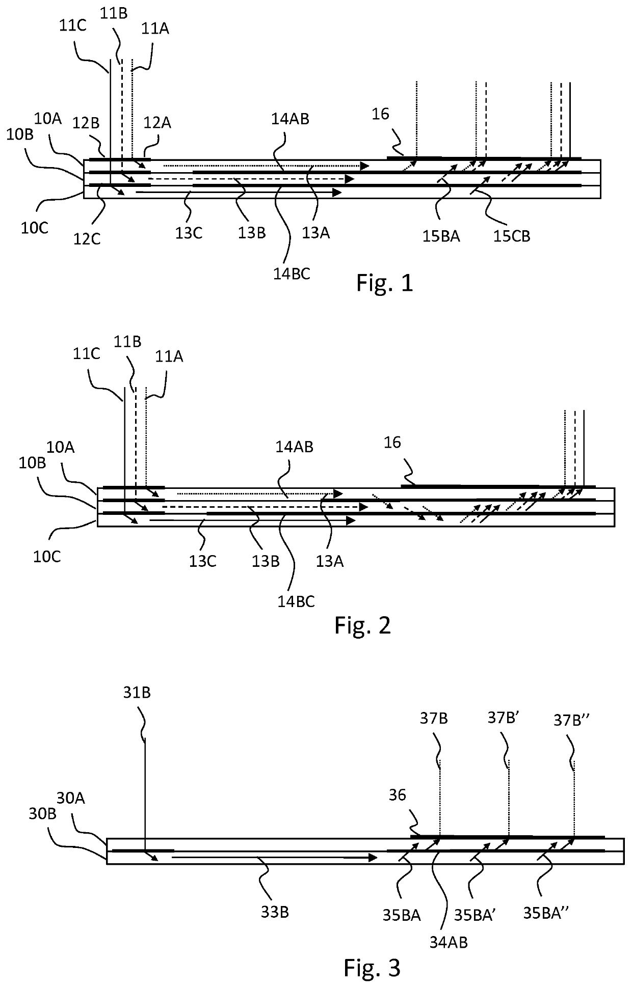
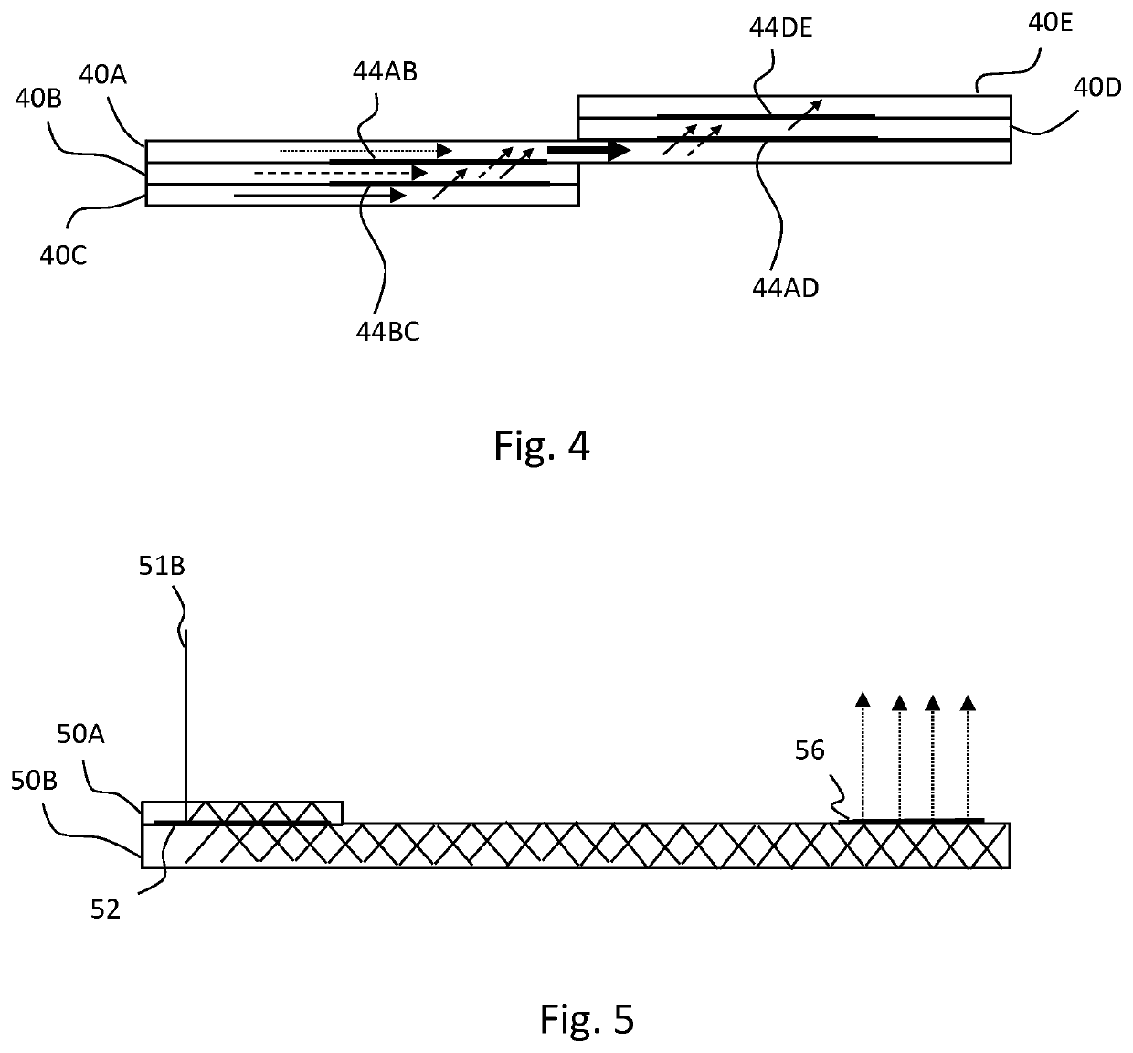
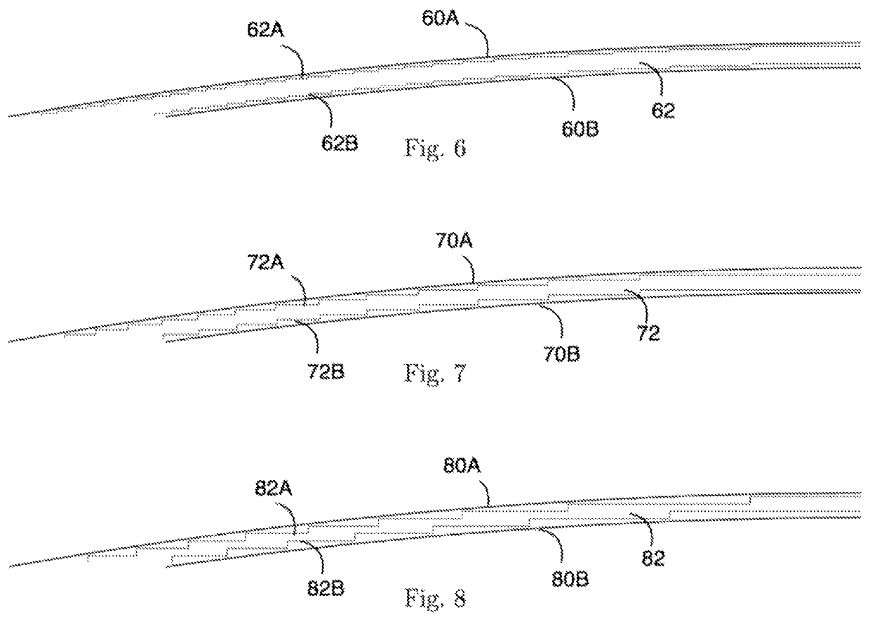
[0029]The term “diffractive optical element” (DOE) refers to a zone of the waveguide body comprising a physical structure capable of diffracting light. The structure typically comprises a pattern of features having a size of 1 μm or less. The DOE may be either periodic or non-periodic and have a constant (single-region) or non-constant diffractive optical response over its area. A non-constant diffractive optical response DOE may be a multi-region DOE.

[0030]The term “intermediate DOE” refers to a DOE that is not intended to out-couple light directly therefrom, but to change the propagation path of light rays from one layer to another. Due to imperfections, a certain amount of out-coupling may, however occur. Typically, at least 90% of propagating light hitting the intermediate DOE continues propagation in either the original layer or the new layer, depending on the predefined optical response.

[0031]“Diffractive optical response” of the DOE refers to the change in th...


PUM

PropertyMeasurementUnit
sizeaaaaaaaaaa
diffractive optical responseaaaaaaaaaa
light power distributionaaaaaaaaaa

Abstract

The invention relates to a waveguide display element for guiding an image from a first lateral zone of the element to a second lateral zone of the element, the element comprising a plurality of waveguide layers (40A-E) on top of each other. The element further comprises at least one intermediate diffractive optical element (44AB, 44BC, 44AD, 44DE) arranged between two of said waveguide layers. The intermediate diffractive optical element (44AB, 44BC, 44AD, 44DE) is adapted to change the distribution of propagating light power between the layers. The invention also concerns a diffractive display device comprising such element.

Description

FIELD OF THE INVENTION[0001]The invention relates to diffractive waveguide display elements, which can be used in personal display devices, such as head-mounted displays (HMDs) and head-up displays (HUDs).BACKGROUND OF THE INVENTION[0002]Diffractive waveguide elements typically comprise a single waveguide layer or a plurality of stacked layers. In the case of several layers, different colors or different parts of the field-of-view of the image to be displayed can be guided in different layers. In that case, each of the layers comprises a separate in-coupling grating for coupling part of the image to the layer, and a separate out-coupling grating for coupling the part of the image out of the element.[0003]US 2017131546 A1, D2_EP 2733517 A1 and CN 106526730 A disclose waveguides, which may have multiple layers.[0004]The disclosed schemes are relatively limited, as concerns the design choices one can make.SUMMARY OF THE INVENTION[0005]It is an aim of the invention to overcome limitatio...

Claims


Application Information

Patent Timeline
Patent Type & Authority Applications(United States)
IPC IPC(8): G02B27/42G02B5/18G02B27/01
CPCG02B5/1828G02B27/4272G02B5/1819G02B27/4205G02B27/0172G02B27/0101G02B6/00
Inventor BLOMSTEDT, KASIMIR
Owner DISPELIX OY
Why Eureka
Try Eureka