Electrical plug-in connector, insulating protective element and method for assembling an electrical plug-in connector

Active Publication Date: 2021-01-21
ROSENBERGER HOCHFREQUENZTECHNIK GMBH & CO KG
View PDF0 Cites 0 Cited by
  • Summary
  • Abstract
  • Description
  • Claims
  • Application Information

AI Technical Summary

Benefits of technology

The present invention is about an electrical plug-in connector that is safe and cost-effective for mass production. It also includes a better insulating protective element to prevent short circuits without increasing assembly expenses. Additionally, the invention provides a method for assembling a safe and cost-effective plug-in connector that can be produced through mass production.

Problems solved by technology

Irrespective of the field of use of the electrical plug-in connector, a short circuit between the internal conductor(s) and the external conductor owing to protruding individual wires of a cable shielding braid is a problem which has already been known for a long time.
In this respect, a design of the electrical plug-in connector in the case of which an insulating part or insulating protective element is arranged between the internal conductor contact elements and the external conductor contact element is comparatively impractical since the options for fastening the internal conductor contact element to the internal conductors of the electrical cable are limited owing to the insulating protective element.
However, owing to the assembly access point, the possibility of a short circuit on account of protruding individual wires of the external conductor shielding braid of the electrical cable arises once again.
This is not acceptable in particular for safety-critical applications, for example for high-voltage plug-in connectors, or for transmitting critical data signals, for example during the course of autonomous operation of a motor vehicle.
However, coating the screw is comparatively complicated and expensive.
Furthermore, a solution of this kind, in particular for safety-critical power cables or high-voltage cables, may sometimes still not be sufficiently reliable.

Method used


Image

  • Electrical plug-in connector, insulating protective element and method for assembling an electrical plug-in connector
  • Electrical plug-in connector, insulating protective element and method for assembling an electrical plug-in connector
  • Electrical plug-in connector, insulating protective element and method for assembling an electrical plug-in connector

Examples


Embodiment Construction

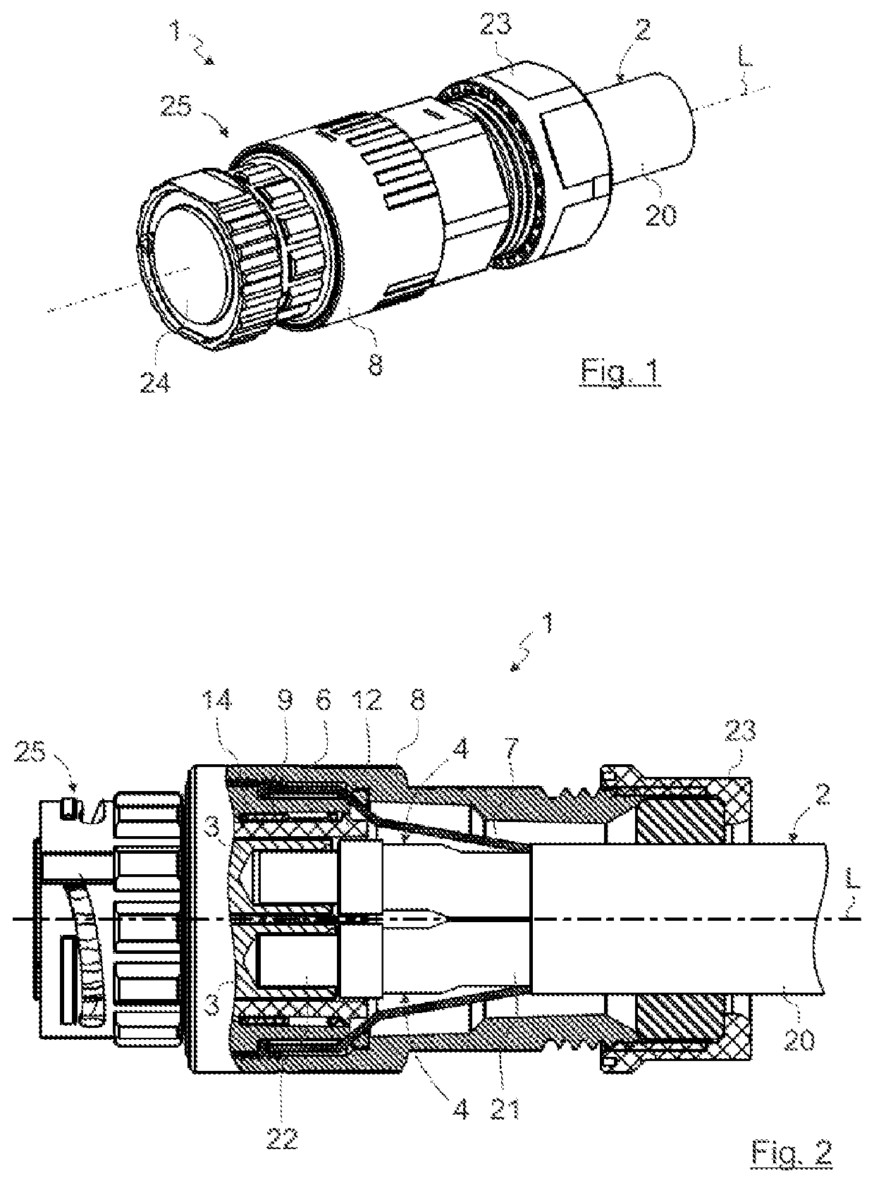
[0134]FIG. 1 shows a perspective illustration of an electrical plug-in connector 1 according to the invention. The electrical plug-in connector 1 is illustrated in a manner connected to an electrical cable 2 by way of example.

[0135]The invention is described, merely by way of example, with reference to embodiments of electrical plug-in connector 1 illustrated in the figures. In principle, an electrical plug-in connector according to the invention can have any desired design, for example a coaxial design, a triaxial design or another design. In the exemplary embodiment, the electrical plug-in connector 1 has, by way of example, a round geometry. However, in principle, the invention can also be suitable for use with a rectangular plug-in connector, for example a flat plug-in connector.

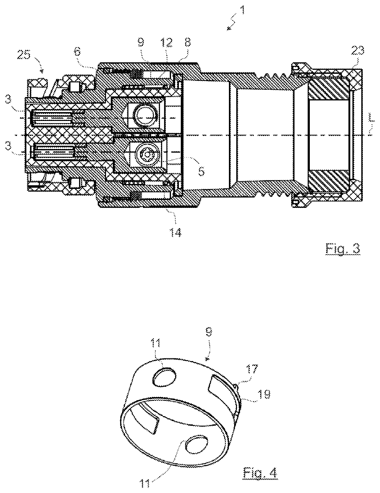
[0136]FIGS. 2 and 3 show sectional illustrations of the plug-in connector 1 illustrated in FIG. 1 in the longitudinal direction, that is to say along the longitudinal axis L or along the center axis of t...


PUM


Abstract

An electrical plug-in connector includes an internal conductor contact element, an external conductor contact element and an insulating protective element arranged between the internal conductor contact element and the external conductor contact element. The external conductor contact element may have a recess for providing an assembly access point for fastening the internal conductor contact element to an internal conductor of an electrical cable. The insulating protective element can be displaced between an assembly position, in which the assembly access point is cleared through the assembly recess to the internal conductor contact element, and an insulating protection position, in which the assembly access point to the internal conductor contact element is blocked by the insulating protective element.

Description

CROSS REFERENCE TO RELATED APPLICATIONS[0001]Priority is hereby claimed under 35 U.S.C. § 119 to European Patent Application No. 19 186 433.9 which was filed in the European Patent Office on Jul. 16, 2019.STATEMENT REGARDING FEDERALLY-SPONSORED RESEARCH OR DEVELOPMENT[0002]Not applicable.INCORPORATION BY REFERENCE[0003]European Patent Application No. 19 186 433.9 which was filed in the European Patent Office on Jul. 16, 2019 is expressly incorporated herein by reference in its entirety to form part of the present disclosure.FIELD OF INVENTION[0004]The invention relates to the field of electrical connectors. More particularly, this invention relates to an electrical plug-in connector having an internal conductor contact element, an external conductor contact element and an insulating protective element which is arranged between the internal conductor contact element and the external conductor contact element and is displaceable between an assembly position and an insulating protectin...

Claims


Application Information

Patent Timeline
IPC IPC(8): H01R13/436H01R13/6592H01R31/06H01R43/20H01R4/30
CPCH01R13/436H01R13/6592H01R2103/00H01R43/20H01R4/305H01R31/06H01R13/42H01R13/422H01R13/426H01R13/6585H01R13/4362H01R13/4368H01R13/447
Inventor FUCHS, JULIANTRUC-VALLET, ELIEWALLNER, MARKUS
Owner ROSENBERGER HOCHFREQUENZTECHNIK GMBH & CO KG
Why Eureka
Try Eureka