Braking caster

Inactive Publication Date: 2021-08-26
FUJIAN ZENITHEN CONSUMER PROD
View PDF0 Cites 0 Cited by
  • Summary
  • Abstract
  • Description
  • Claims
  • Application Information

AI Technical Summary

Benefits of technology

The invention is a braking system that uses a minimal number of parts and operates using simple and reliable methods. It makes use of the difference in radius between the pivot point of the spring and the spring swing, as well as the unstable status caused by the spring swinging with the brake plate. The brake handle bypasses this unstable status, allowing for stable braking and released state without the need for extra parts or coordination.

Problems solved by technology

The overall structure is complicated and there are many associated mechanisms, and it is difficult to be applied in confined spaces.

Method used


Image

  • Braking caster
  • Braking caster
  • Braking caster

Examples


Embodiment Construction

)

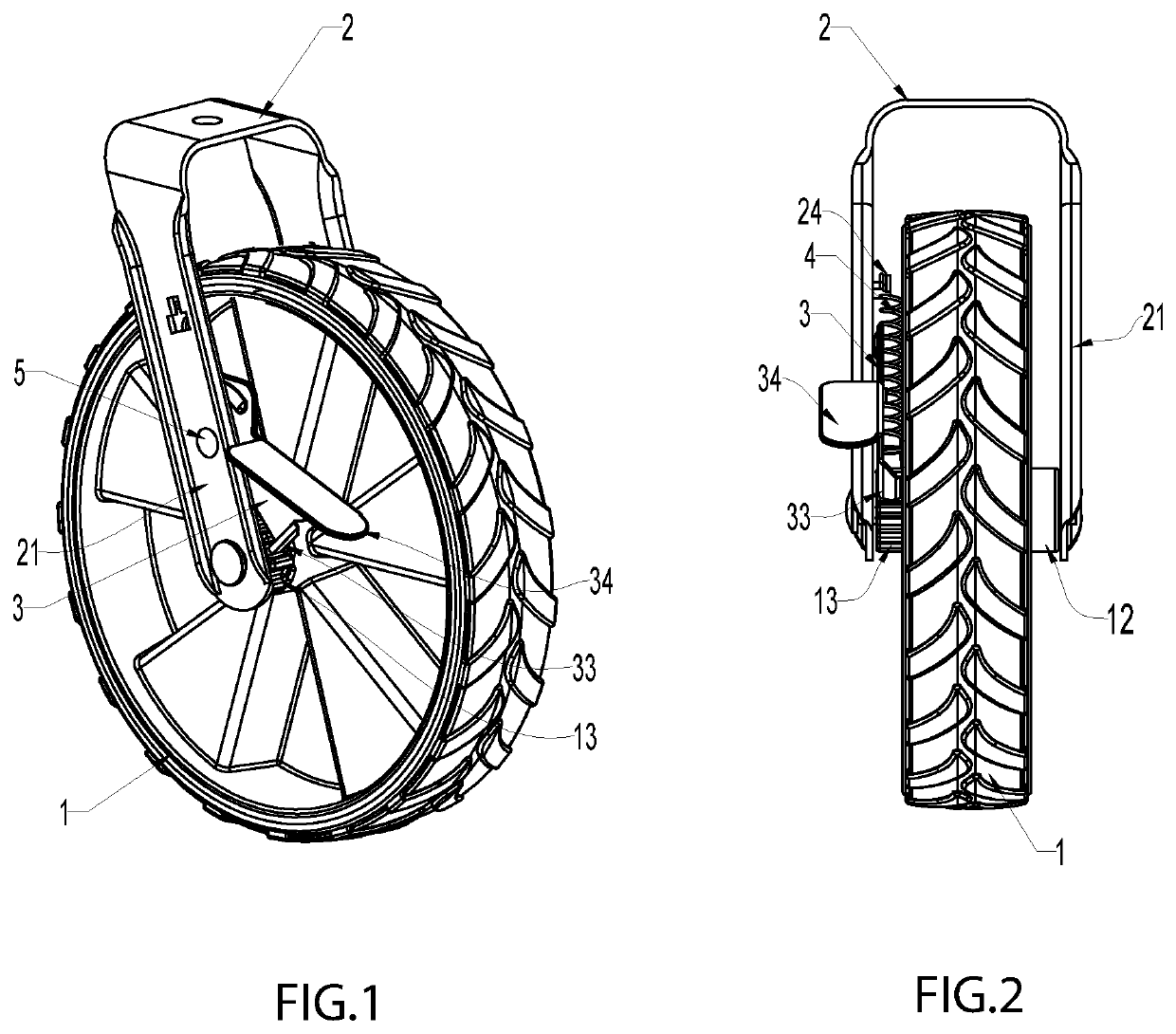
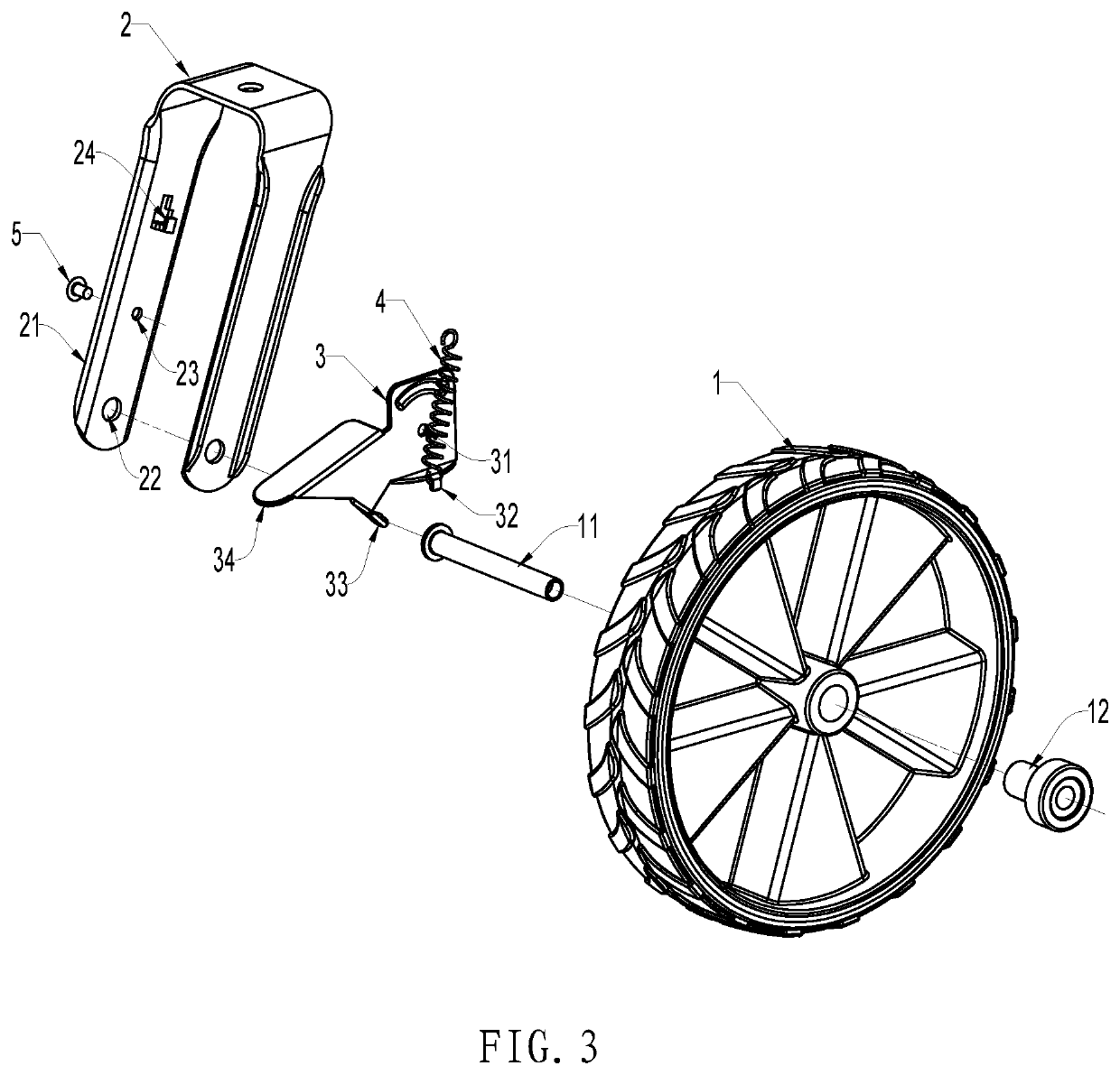
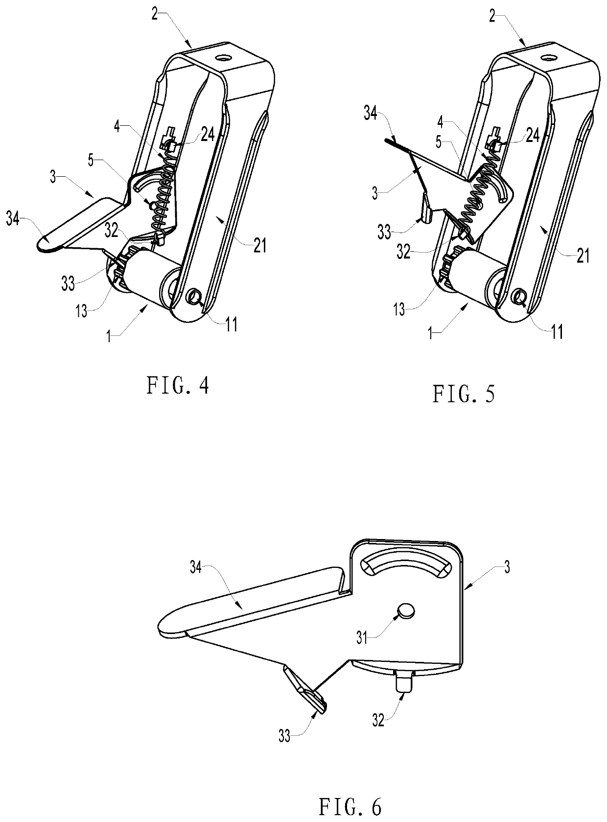
[0036]Referring to FIGS. 1-3, a type of braking caster is shown that includes casters 1, frame 2, braking plates 3, and springs 4. The casters 1 are hinged to the frame 11 through the wheel axles 11. Braking of the casters is achieved by braking plates 3. In this example, the caster 11 and wheel axle 11 have a separate structure. The caster 1 can freely rotate relative to the wheel axle 11. There can be a bearing or axle sleeve 12 between them to reduce abrasion and decrease friction. Wheel axle 11 can be directly locked to the frame 2 or directly riveted. To achieve braking, one side of a caster 1 has a brake gear 13 or the axle sleeve can have a brake gear 13 linked to the caster 1 by the axle sleeve. In other words, linkage is achieved by the coordination of the spline and top pin. Depending on the situation, the frame 2 can be formed from plastic, or in this example, the frame 2 is formed from punch-sheared steel plate and bent to form a U-shaped structure. The ends of the two ...


PUM


Abstract

A braking caster is provided that includes casters, a frame, braking plates, and springs. One end of a spring is hung on to the spring hook of the brake plate, and the other end is hung on to the frame. As the unstable status is caused by the spring swinging with the brake plate to the position of the rivet, the manually driven brake handle bypasses the unstable status, and can achieve stable braking and released statuses.

Description

BACKGROUND OF THE INVENTIONField of the Invention[0001]This invention belongs to the field of casters for luggage and push carts, and particularly involves a type of braking caster. Specifically, it utilizes brake plates and spring action to stably maintain a braking or released condition.Technical Background[0002]China patent application CN201210359173.3 discloses a type of braking caster. It includes a caster frame and turnable wheels on the caster frame. The wheels have wheel clutches. The frame has movable brake plates, and the brake plates have brake clutches. When the brake plates move back and forth, they can utilize the brake clutches and the wheel clutches to brake or release the wheels. There are elastic resets for the brake plates between the brake plates and the caster frame. Brake pedals are hinged to the caster frame. A pushing device is located on each hinge axis and can be driven by the hinge axis to push the brake plates back and forth. The pushing device includes a...

Claims


Application Information

Patent Timeline
IPC IPC(8): B60B33/00
CPCB60B33/0084B60B33/0039B60B2200/43
Inventor FRANKEL, ANDREW DAVIDZHENG, SHI-PINGZHENG, TIAN-XIA
Owner FUJIAN ZENITHEN CONSUMER PROD
Why Eureka
Try Eureka