Automatic pressure valve for inflation / deflation of a pneumatic arrangement

a pneumatic arrangement and automatic technology, applied in the direction of mechanical equipment, transportation and packaging, valve types, etc., can solve the problems of safety problems or immobilization of vehicles, maintenance of tyre pressure in vehicles, and pressure loss, and achieve the effect of reducing pressure differences

Active Publication Date: 2022-01-13
COL VEN
View PDF0 Cites 0 Cited by
  • Summary
  • Abstract
  • Description
  • Claims
  • Application Information

AI Technical Summary

Benefits of technology

[0008]It is still an object of this invention to provide an automatic valve having a single movable part that bette...

Problems solved by technology

The control, regulation and maintenance of the tyre pressure in vehicles in motion o in stationary vehicles is an issue that has been developed in the last years.
These arrangements are ordinarily called central systems of tyre inflation—deflation, for example of trucks, some of which are intended for tractors and others, for trailers, all of which require a big pipe for a fast inflation and deflation since air has to circulate along the pipe to the control central during both inflation and deflation, which besides causing pressure loss problems, it originates safety problems or immobilization of the vehicle in case of leaks or breaks in the pipe since it is directly connected to the tyre.
Between the sha...

Method used


Image

  • Automatic pressure valve for inflation / deflation of a pneumatic arrangement
  • Automatic pressure valve for inflation / deflation of a pneumatic arrangement
  • Automatic pressure valve for inflation / deflation of a pneumatic arrangement

Examples


example 1

[0024]Start-up. Initial conditions: Pneumatic tyre pressure: 100 psi; state of the automatic valves of this invention 101: “Blockage”; pressure in the feeding network of each shaft: 0 psi. Calibration pressure of the equipment 201: 100 psi.

[0025]The driver gets into the truck and starts the engine to begin the journey, for example, to a construction site. To such effect, the equipment 201 is active and waiting for the pressure generated by the vehicle compressor (inlet pressure) to be proper to begin working. The automatic valves 101 arranged in each pneumatic tyre are at the moment in a retention status since there is not air pressure in the feeding network of each shaft.

[0026]A reading panel 202 (FIG. 6) has a lit LED which indicates that the equipment is in a high-pressure status (HIGH). The reading panel also shows that the pressures present in each shaft 203 and the inlet pressure that fees equipment 201. For example: Shaft 1: 100 psi. Shaft 2: 100 psi. Shaft 3: 100 psi. Inlet ...

example 2

[0029]Load to a given value of the tyre of the above-mentioned example. Initial conditions: Tyre pressure: 100 psi. Automatic valve status: retention under equal pressure. Pressure in the feeding network of each shaft: 100 psi. Calibration pressure of the equipment 201: 30 psi. It is the pressure the tyres will reach at the end of this status.

[0030]Initially, the reading and tyre pressure control panel 202 (FIG. 6) shows the following status: the pressures of each shaft 203 is of 100 PSI. The LED is lit which indicates that the equipment is at a high-pressure status (HIGH). Valves 101 are in a retention status under equal pressure of the network and the tyre. When pressing on a key H / L, a shift in the equipment status from high to low pressure happens and the LED turns on. In order that deflation is caused, it is necessary that the valves shift to a blockage status. To such an effect, a depressurization module 204 activates so that the pressure in the network of each shaft falls dow...

example 3

[0035]Tyre inflation. Initial conditions: Tyre pressure: 30 psi. Valve estate IRD: retention under equal pressure. Pressure in the feeding network of each shaft: 30 psi. Calibration pressure of the equipment 201: 100 psi. This is the pressure the tyres will reach at the end of this status.

[0036]Initially, the panel (FIG. 6) shows the following status: the pressures of each shaft 203 is of 30 PSI. The LED is lit which indicates that the equipment is at low pressure (LOW). The valves 101 are in a retention status under equal pressure of the network and the tyre. When the key H / L is pressed, the status shift of the equipment happens from low to high pressure. It is at this moment when the LED turns on and the equipment 201 starts inflating the tyres from 30 PSI to 100 PSI.

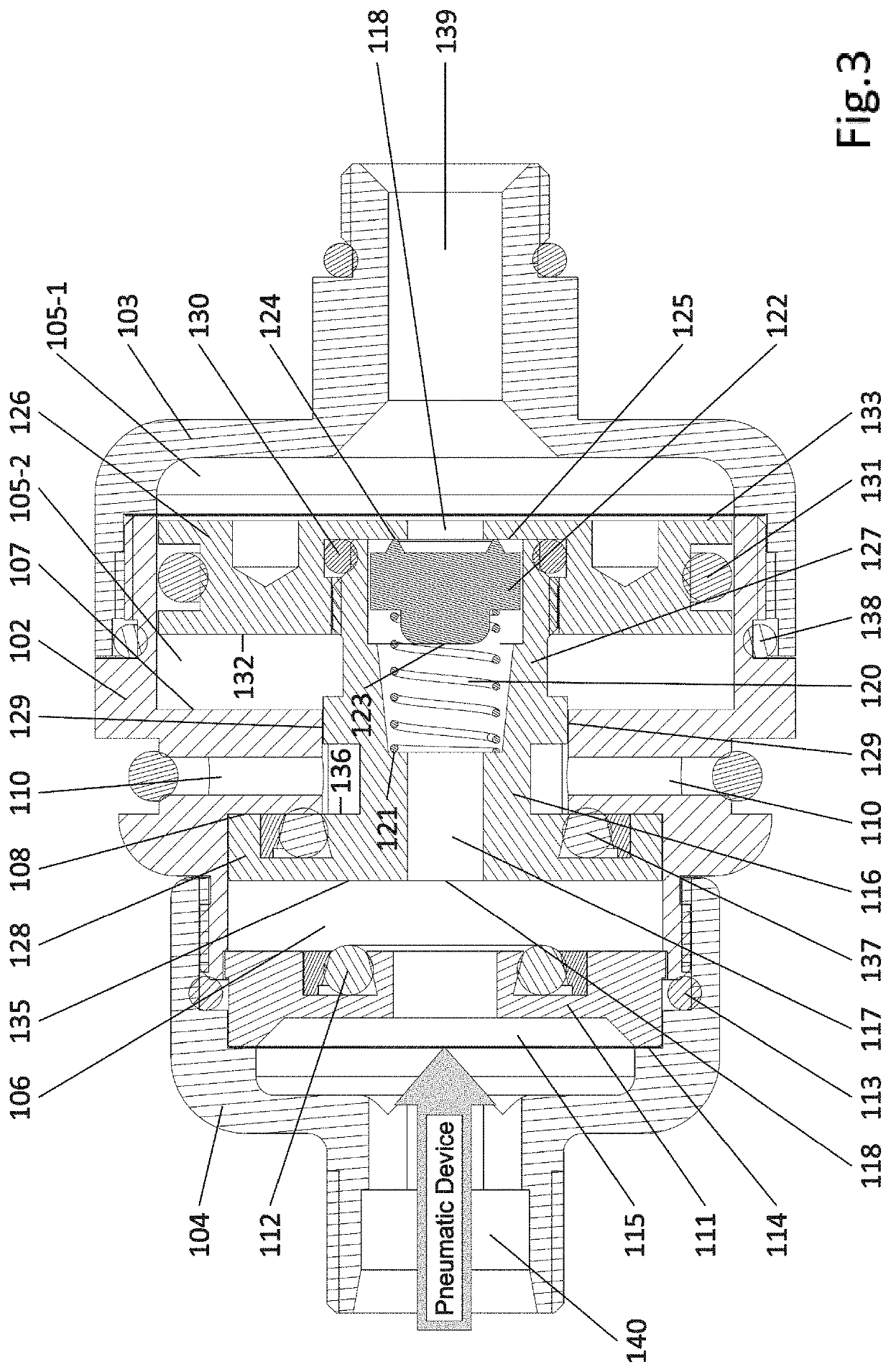
[0037]According to FIG. 5, the valves are in an inflation status. When pressurized air is supplied at a desired pressure in the inlet path 139, said desired pressure being greater than the calibration pressure of the ...


PUM


Abstract

An Automatic pressure valve for the inflation—deflation of pneumatic arrangements comprises a main body (102) with an inlet connector (103) communicated with a pressurized air supply network an outlet connector connected to a pneumatic arrangement and a mechanical means which allows for a total or partial air passage or blockage to perform inflation—deflation operations of the pneumatic arrangement in a faster and practical way. The mechanical means comprises a main movable plunger (116) having an inner stepped through channel (117), a spring (120) arranged on a seat (121) defined in the inner stepped channel (117), an inflation plunger (122) operatively retained by said spring (120), a proximal movable end (126) within a first inner chamber (105), a reduced middle section (119), and a distal movable end (128) having a smaller diameter than the proximal end (126) and arranged within a second inner chamber (106)

Description

FIELD OF THE INVENTION[0001]This invention relates to pressure control, regulation and calibration equipment in a pneumatic pressure arrangement and, more particularly, to an automatic pressure valve for the inflation / deflation of pneumatic arrangements which provides greater inner stability during inflation / deflation operations and, in the case of the use of the automatic pressure valve in tyres, it is intended to avoid the premature wear of the mechanical parts by adjusting the pressure to the ground or to grip requirements and also to obtain through a relationship among relative inner pressure differences in a faster and more practical and effective way the calibration of the tyre pressure of vehicle wheels according to the different uses and related circumstances.PRIOR ART DESCRIPTION[0002]The control, regulation and maintenance of the tyre pressure in vehicles in motion o in stationary vehicles is an issue that has been developed in the last years. The maintenance increase or r...

Claims


Application Information

Patent Timeline
IPC IPC(8): B60C29/00B60C23/00F16K15/20
CPCB60C29/002F16K15/20B60C23/001Y10T137/3646
Inventor COLUSSI, PRIMO ANTONIOVENICA, NATALIO DOMINGO
Owner COL VEN
Why Eureka
Try Eureka