Motor and disk drive device

A technology of motors and dynamic pressure bearings, applied in the direction of electromechanical devices, electric components, casings/covers/supports, etc., can solve problems such as complex lubricating oil design, and achieve the effect of suppressing pressure differences

Inactive Publication Date: 2014-09-10
NIDEC CORP
View PDF6 Cites 0 Cited by
  • Summary
  • Abstract
  • Description
  • Claims
  • Application Information

AI Technical Summary

Problems solved by technology

As a result, the design to prevent leakage of lubricating oil is complicated

Method used


Image

  • Motor and disk drive device
  • Motor and disk drive device
  • Motor and disk drive device

Examples


Embodiment Construction

[0025] In this specification, the upper side in the central axis direction of the motor is simply referred to as "upper side", and the lower side in the central axis direction of the motor is simply referred to as "lower side". In addition, the vertical direction does not refer to the positional relationship and direction when actually assembled in the device. In addition, the direction parallel or substantially parallel to the central axis is referred to as "axial direction", the radial direction centered on the central axis is simply referred to as "radial direction", and the circumferential direction centered on the central axis is simply referred to as "circumferential direction". Towards".

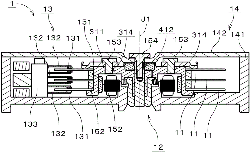
[0026] figure 1 It is a longitudinal sectional view of a disk drive device 1 including a spindle motor (hereinafter simply referred to as "motor") according to an exemplary first embodiment of the present invention. The disk drive device 1 is a so-called hard disk drive device. The...


PUM


Abstract

The present invention provides a motor and a disk drive device, and the motor includes a stationary portion and a rotating portion. The stationary portion includes a shaft portion and an outer cylindrical portion. The rotary portion includes an inner cylindrical portion, an upper annular portion located on the upper side of the inner cylinder portion, and a lower hub annular portion. An upper seal portion is formed between the shaft portion and the upper portion of the upper annular portion. A first gap is formed between the shaft portion and the upper annular portion and the inner cylinder portion, and a radial dynamic pressure bearing portion is arranged in the first gap. A second gap is formed between the inner cylinder portion and the outer cylinder portion. A third gap is formed between the lower surface of the upper annular portion and the upper surface of the outer cylindrical portion, and a thrust dynamic pressure bearing portion is arranged in the third gap. A lower seal portion is formed between the annular portion of the outer cylindrical portion and the lower hub annular portion. Further, the upper annular portion comprises a communicating path. The communicating path communicates the region between the upper sealing portion and the radial dynamic pressure bearing portion and the region radially closer to the outer side than the thrust dynamic pressure bearing portion in the third gap.

Description

technical field [0001] The present invention relates to electric motors. Background technique [0002] Conventionally, as a motor of a disk drive device, there has been a bearing mechanism utilizing fluid dynamic pressure. The hydrodynamic fluid bearing device for a spindle motor disclosed in JP 2007-162759 A includes a shaft main body and a cylindrical sleeve main body into which the shaft main body is inserted. The shaft main body is fixed to the base plate of the motor. The sleeve body is fixed to the rotor of the motor. The shaft main body is provided with annular first and second thrust flanges located on the upper side and the lower side of the sleeve main body. In the dynamic pressure fluid bearing device, a radial bearing portion is formed between the shaft main body and the sleeve main body. A thrust bearing portion is formed between each of the two thrust flanges and the sleeve main body. In addition, a communication hole that communicates the two thrust gaps ...

Claims


Application Information

Patent Timeline
Patent Type & Authority Patents(China)
IPC IPC(8): H02K5/16G11B17/022
Inventor 水上顺也关井洋一近野洋
Owner NIDEC CORP
Why Eureka
Try Eureka