Liquid ejection device

a liquid ejection device and liquid ejection technology, which is applied in the direction of printing, other printing apparatus, etc., can solve the problems of difficult to match the negative pressure given to the recess that suctions the end part of the paper and the negative pressure given to the recess that suctions the paper, and it is not possible to suction the paper to the medium support surface stably

Inactive Publication Date: 2014-06-24
SEIKO EPSON CORP
View PDF38 Cites 0 Cited by
  • Summary
  • Abstract
  • Description
  • Claims
  • Application Information

AI Technical Summary

Benefits of technology

[0010]With this arrangement, the negative pressure given to the negative pressure chamber partitioned in the width direction orthogonal to the transport direction of the ejection medium is given to the second recess that suctions the end part of the ejection medium, and to the adjacent first recess further to the inside of the ejection medium than the second recess. Therefore, it is possible to have the suction force of the second recess that suctions the ejection medium be a suction force according to the suction force at the first recess, so it is possible to stably support the ejection medium on the medium support surface using suction.
[0014]With this arrangement, it is possible to make the flow of air suctioned to the negative pressure chamber uniform in the direction orthogonal to the transport direction, so at the plurality of first recesses arranged in the direction orthogonal to the transport direction, it is possible to suppress a pressure difference in the negative pressure given from the negative pressure chamber due to the arrangement positions.
[0016]With this arrangement, the air suctioned from the suction holes meanders and flows to the negative pressure chamber, so it is possible to make the flow of air suctioned to the negative pressure chambers uniform. Therefore, it is possible to suppress a difference in pressure of the negative pressure given from the negative pressure chambers to the plurality of first recesses.
[0018]With this arrangement, the air suctioned from the communication unit meanders via the vent hole and flows to the negative pressure generating unit, so when liquid is suctioned from the suction hole, it is possible to inhibit liquid suctioned from the negative pressure chamber to the negative pressure generating unit from flowing to outside the negative pressure generating unit.

Problems solved by technology

However, with the constitution of the medium support unit disclosed in the above mentioned publication, there is communication with negative pressure chambers for which the recess that suctions the end part of the paper in the width direction of the paper and the recess that suctions further to the inside than the paper end part are different, so it is difficult to match the negative pressure given to the recess that suctions the end part of the paper and the negative pressure given to the recess that suctions further to the inside than the paper end part.
Therefore, since it is not possible to suction with stability evenly up to the paper edge part in the paper width direction, there is the risk that it will not be possible to suction the paper to the medium support surface stably.

Method used


Image

  • Liquid ejection device
  • Liquid ejection device
  • Liquid ejection device

Examples


Embodiment Construction

[0029]Following, as an embodiment with the present invention in a specific example, we will describe an inkjet printer (hereafter referred to simply as “printer”) as an example of a liquid ejection device, equipped with a liquid ejection head for ejecting liquid, for forming (printing) an image or the like containing text or graphics by ejecting liquid on paper (roll paper) as an ejection medium, while referring to the drawings.

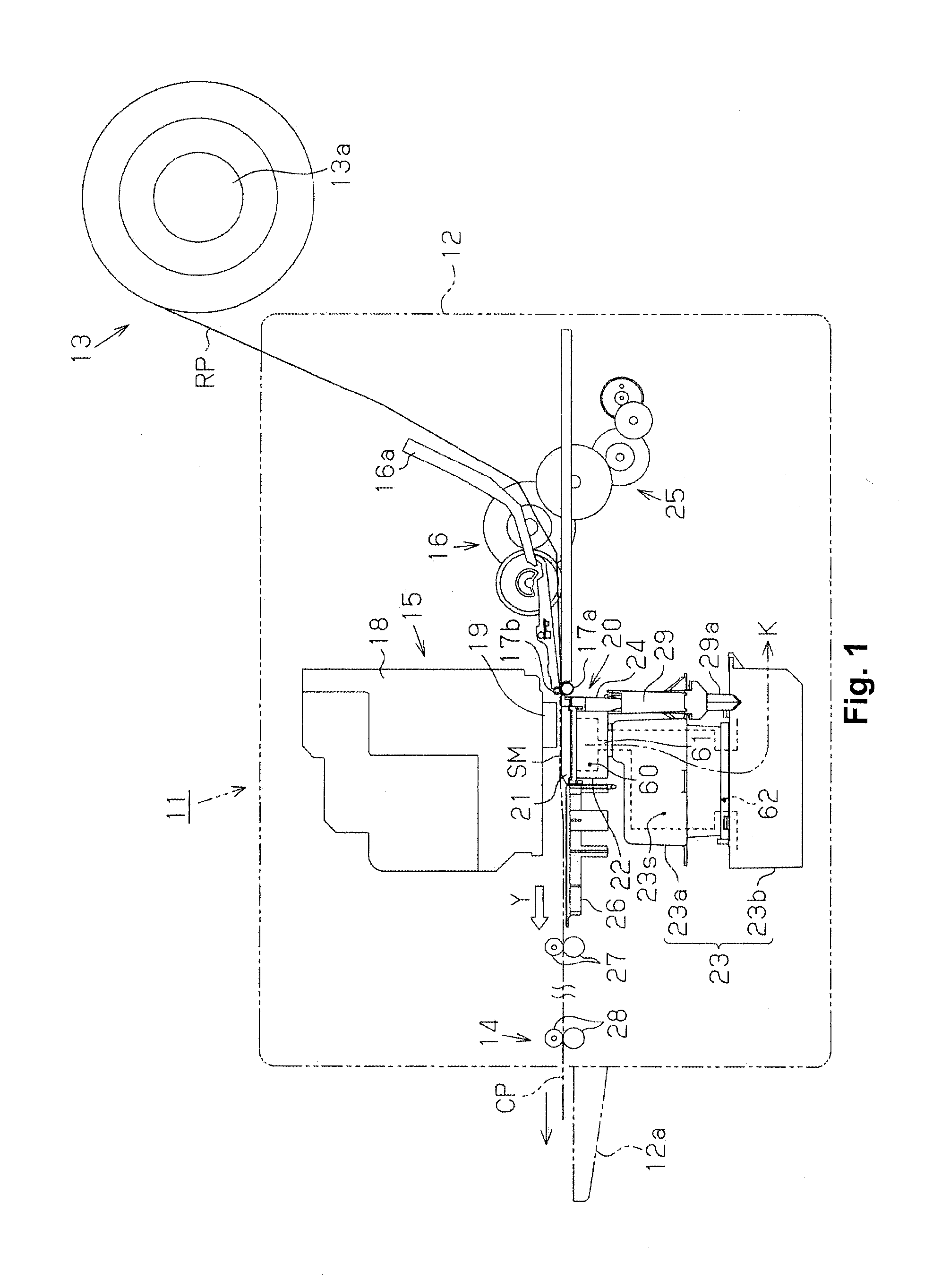
[0030]As shown in FIG. 1, the printer 11 has a main unit case 12, and a paper supply unit 13 with the long sheet form paper RP supplied to the main unit case 12 equipped in a rolled state. Equipped inside the main unit case 12 are a liquid ejection unit 15 that ejects liquid on the supplied paper RP to form an image or the like, and a paper ejection unit 14 for ejecting from a paper ejection port provided on the main unit case 12 to a paper ejection tray 12a the paper RP on which an image or the like is formed as cut paper CP.

[0031]The paper supply unit 13 is...


PUM


Abstract

A medium support unit of a liquid ejection device has a negative pressure chamber and a medium support surface so that an ejection medium is supported on the medium support surface by suction, and includes a plurality of first recesses and at least one second recess. The first recesses are in communication with a negative pressure generating unit, and aligned along a width direction. The second recess is disposed at a position corresponding to an end part in the width direction of the ejection medium, and arranged to accept liquid ejected from a liquid ejection head. The second recess is in communication with an adjacent one of the first recesses at a position inward of the end part of the ejection medium. The first recesses are respectively in communication with the negative pressure generating unit via the negative pressure chamber partitioned into a plurality of units in the width direction.

Description

CROSS-REFERENCE TO RELATED APPLICATIONS[0001]This application claims priority to Japanese Patent Application No. 2012-046265 filed on Mar. 2, 2012. The entire disclosure of Japanese Patent Application No. 2012-046265 is hereby incorporated herein by reference.BACKGROUND[0002]1. Technical Field[0003]The present invention relates to a liquid ejection device for ejecting a liquid on an ejection medium that is supported by suction on a medium support unit.[0004]2. Related Art[0005]From the past, inkjet printers (hereafter referred to simply as “printers”) have been put to practical use as liquid ejection devices for ejecting ink as a liquid from a liquid ejection head onto paper as one type of ejection medium that is transported while being supported on a medium support unit, and forming an image containing text or graphics. With this type of printer, on a medium support surface that the medium support unit has, a plurality of indented recesses are arranged in the direction orthogonal t...

Claims


Application Information

Patent Timeline
Patent Type & Authority Patents(United States)
IPC IPC(8): B41J2/01
CPCB41J11/0065B41J11/0085B41J11/06
Inventor YAMAMOTO, TAKAO
Owner SEIKO EPSON CORP
Why Eureka
Try Eureka