Rotating electrical machine winding, rotating electrical machine, and semiconductive insulating component used therein

a technology of rotating electrical machines and rotating electrical machines, which is applied in the direction of insulated conductors, power cables, cables, etc., can solve the problems of difference in potential, inability to suppress corona discharge completely, and discontinuousness

Active Publication Date: 2008-05-08
MITSUBISHI HEAVY IND LTD
View PDF7 Cites 32 Cited by
  • Summary
  • Abstract
  • Description
  • Claims
  • Application Information

AI Technical Summary

Benefits of technology

[0010]An object of the present invention is to provide a rotating electrical machine winding that can not only prevent corona discharges attributable to peeling and cracks that occur during the curing of insulation resin but also can be supported stably against an electromagnetic force, as well as a rotating electrical machine that uses the rotating electrical machine winding.
[0013]The semiconductive insulating layer is mechanically continuous because it is formed by lap-winging a continuous semiconductive sheet, which is center-folded in the longitudinal direction, so the rotating electrical machine winding is supported by the rotating electrical machine core through the continuous semiconductive insulating layer. The supporting force is thereby large and stable. It then becomes possible to obtain a rotating electrical machine winding that can be supported stably against an electromagnetic force and a rotating electrical machine using the rotating electrical machine winding.

Problems solved by technology

In this semiconductive insulating layer, however, even when the two components are lap-wound, they become discontinuous because of the presence of the separated layer.
It is unavoidable that a difference in potential occurs due to peeling or another defect caused in the discontinuous part.
As a result, corona discharges cannot be suppressed completely.
Since the supporting force is small and the electromagnetic force is repeated, however, the rotating electrical machine is supported unstably, resulting in vibration, noise, or insulation resin damage.

Method used


Image

  • Rotating electrical machine winding, rotating electrical machine, and semiconductive insulating component used therein
  • Rotating electrical machine winding, rotating electrical machine, and semiconductive insulating component used therein
  • Rotating electrical machine winding, rotating electrical machine, and semiconductive insulating component used therein

Examples


first embodiment

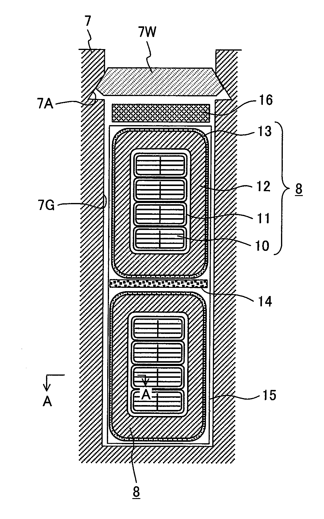
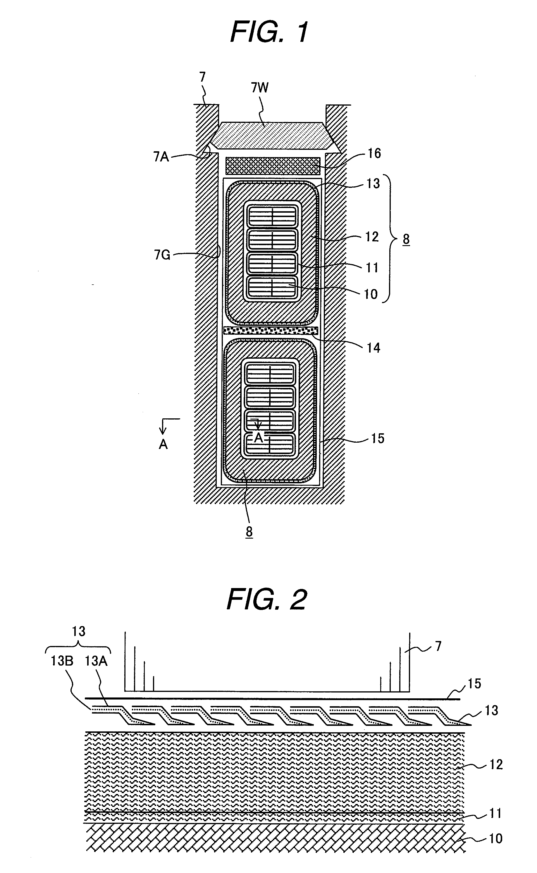
[0026]the inventive rotating electrical machine will be described as for the power generator shown in FIGS. 1 to 3.

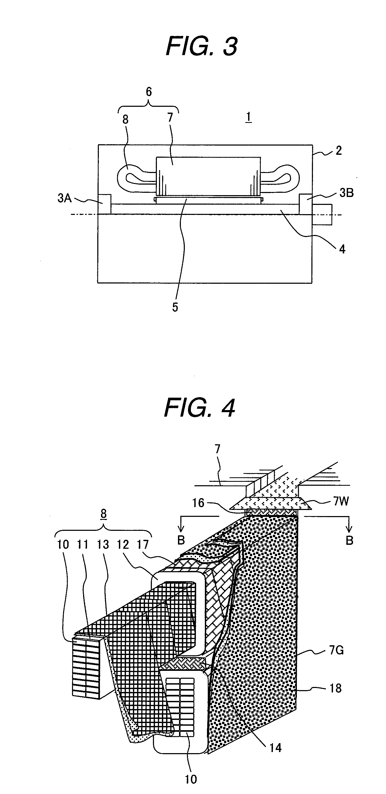
[0027]As shown in FIG. 3, the power generator 1 comprises a housing 2, a rotational axis 4 that is rotatably supported by the housing 2 through bearings 3A and 3B, a rotor 5 that is supported by the rotational axis 4 and has magnetic poles, and a stator 6 that is disposed opposite to the rotor 5 with a spacing left therebetween in the peripheral direction.

[0028]The stator 6 comprises a stator core 7 supported by the housing 2 and a stator winding 8 formed on the stator core 7.

[0029]In this embodiment and other embodiments described later, the stator core 7 and stator winding 8 correspond to the rotating electrical machine core and rotating electrical machine winding in the present invention, respectively.

[0030]The stator core 7 has a plurality of slots 7G spaced at equal intervals in the peripheral direction over the entire length of the stator core 7, from the inner di...

second embodiment

[0042]the inventive rotating electrical machine will be described below with reference to FIGS. 4 and 5. The same structural members as in FIGS. 1 to 3 are assigned the same reference characters, and their details will not be explained again.

[0043]This embodiment differs from the first embodiment in that the semiconductive insulating layer 13 is disposed between the inter-layer insulating layer 11 and the groundwall insulating layer 12, a corona shield layer 17 is formed around the outer periphery of the groundwall insulating layer 12, and another protective insulation 18 is provided around the outer periphery of the corona shield layer 17.

[0044]The semiconductive insulating layer 13 has the same structure and is wound in the same way as in the first embodiment, so its detailed explanation will be omitted.

[0045]The corona shield layer 17 is formed by wrapped taping a polyester nonwoven fabric in which carbon filler are blended, the surface of the polyester nonwoven fabric being coat...

third embodiment

[0051]FIG. 6 illustrates the inventive rotating electrical machine. The same structural members as in FIGS. 4 and 5 are assigned the same reference characters, and their details will not be explained again.

[0052]This embodiment differs from the second embodiment in that a thermal stress relaxation layer 13C, which is an elastic body comprising, for example, such as, silicone rubber in which carbon filler are mixed, is provided inside the center-folded continuous semiconductive sheet 13A.

[0053]In this embodiment as well, the same effect as in the above embodiments can be obtained.


PUM

PropertyMeasurementUnit
semiconductiveaaaaaaaaaa
thermal stress relaxationaaaaaaaaaa
insulatingaaaaaaaaaa

Abstract

When a rotating electrical machine winding is inserted into a slot with a protective insulation intervening between them, a semiconductive insulating layer is lap-wound between an interlayer insulating layer of the rotating electrical machine winding and the protective insulation, the semiconductive insulating layer being formed by center-folding a continuous semiconductive sheet in the longitudinal direction. A thermal stress relaxation layer is provided inside the center-folded continuous semiconductive sheet so that thermal stress exerted in thickness direction of the insulating layers is absorbed.

Description

CLAIM OF PRIORITY[0001]The present application claims priority from Japanese application serial No. 2006-301467, filed on Nov. 11, 2006, the content of which is hereby incorporated by reference into this application.FIELD OF THE INVENTION[0002]The present invention relates to a rotating electrical machine winding and a rotating electrical machine as well as a semiconductive insulating component used in them and, more particularly, to a rotating electrical machine winding and rotating electrical machine that are suitable when insulation resin is grobal impregnated into a rotating electrical machine core in which a rotating electrical machine winding is included as well as a semiconductive insulating component used therein.BACKGROUND OF THE INVENTION[0003]When a rotating electrical machine winding is seated in a slot formed in a rotating electrical machine core in a rotating electrical machine, such as an induction motor or electric generator, that is rated at higher than 3 kV, the gr...

Claims


Application Information

Patent Timeline
Patent Type & Authority Applications(United States)
IPC IPC(8): H02K3/30H01B1/04H02K3/34H02K3/40H02K3/487
CPCH02K3/40H01B1/24
Inventor HIGASHIMURA, YUTAKAKURAHARA, YOSHIMIMIYAO, HIROSHISUZUKI, KEIJIONODA, MITSURUTANAKA, NOBUAKI
Owner MITSUBISHI HEAVY IND LTD
Why Eureka
Try Eureka