Liquid pump with a claw pole stator

a technology of liquid pump and stator, which is applied in the direction of piston pump, magnetic circuit rotating parts, magnetic circuit shape/form/construction, etc., can solve the problems of affecting the stability of the suspension of the rotor and the loss of the magnetic circui

Inactive Publication Date: 2003-01-14
ROBERT BOSCH GMBH
View PDF11 Cites 34 Cited by
  • Summary
  • Abstract
  • Description
  • Claims
  • Application Information

AI Technical Summary

Problems solved by technology

The cylindrical wall between the stator and the rotor is quite thin, so that the gap width will be only s...

Method used


Image

  • Liquid pump with a claw pole stator
  • Liquid pump with a claw pole stator
  • Liquid pump with a claw pole stator

Examples


Embodiment Construction

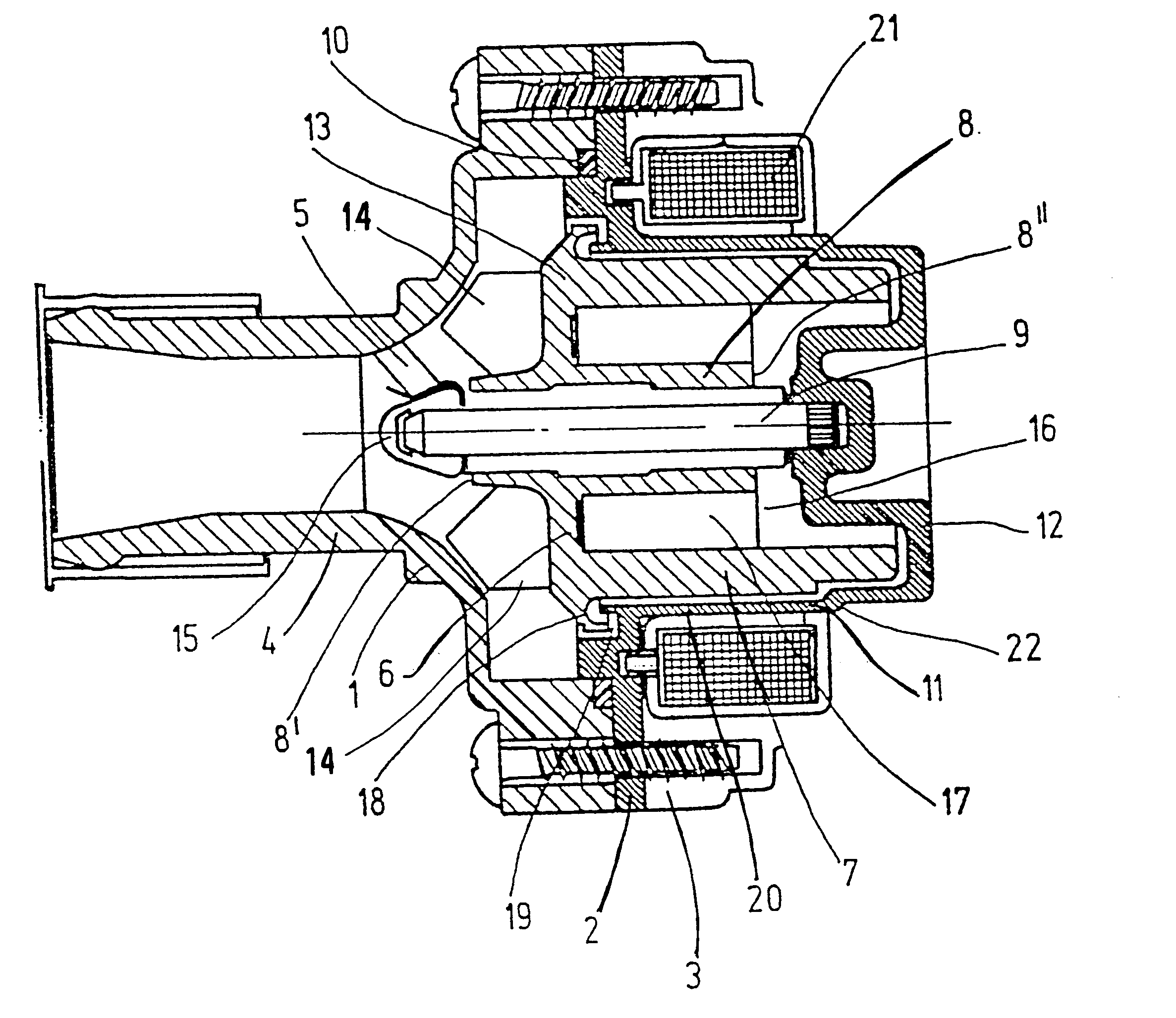
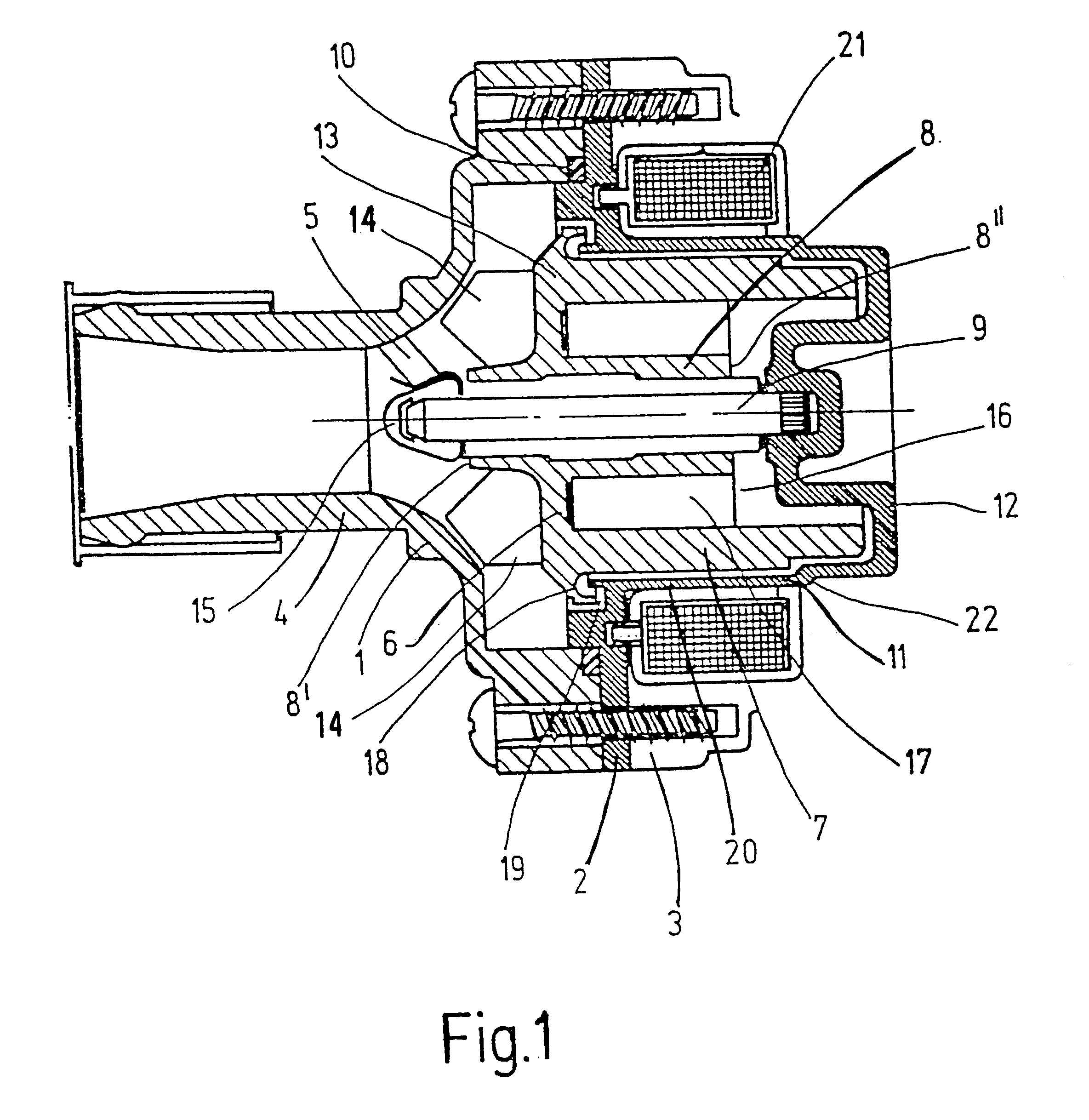
FIG. 1 shows a coolant pump of the invention in an axial section. The pump has a three-piece housing, which comprises a front housing part with a suction neck 4 embodied on it, and a compression neck, not shown, a partition 2, and a rear housing part 3, this last part not being shown completely in the drawing. Parts 1, 2, 3 are held together by screws, which keep the partition 2 fastened between the front part 1 and rear part 3. A sealing ring 10 is clamped between the front housing part 1 and the partition 2. The partition 2 comprises a nonmagnetic material and has a thin-walled portion in the form of a pipe 11, which together with a bottom 12 forms a cup in which a rotor 6 is accommodated.

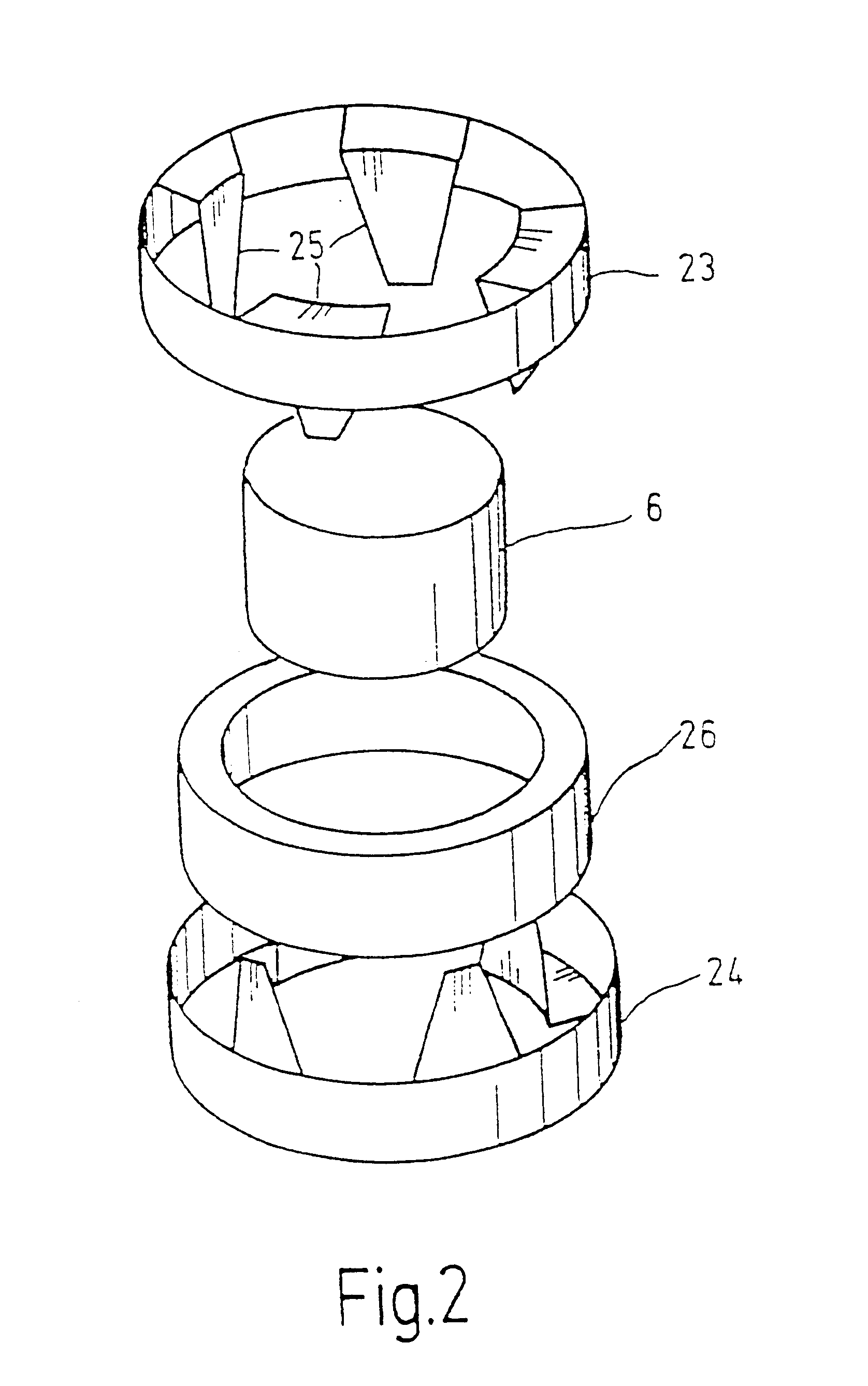
The rotor 6 is made in one piece, for example by injection molding, of a plastic-bonded magnetic material, for instance powdered magnetic material embodied in a synthetic resin matrix or plastic matrix, and it includes an outer cylinder 7 that with only slight spacing follows the course of the pi...


PUM


Abstract

A fluid pump, in particular for the coolant and heating system of a motor vehicle, has a stator (21) of claw pole construction and a rotor (6), separated from the stator (21) by a pipe (11), which is immersed in the coolant and forms a vane wheel. The rotor (6) is disposed radially inside the stator (21).

Description

PRIOR ARTThe invention relates to an electrically operated fluid pump, in particular a coolant pump for the coolant system / heating system of a motor vehicle, with a stator and with a rotor, separated from the stator by a pipe, that is immersed in the coolant and carries a vane wheel.The principle of separating the stator and rotor by a pipe, which makes it possible to dispose the rotor immersed in the coolant, is known from German Patent DE 3 702 028 C2.A more-detailed description of such a pump can be found in German Patent Disclosure DE 44 11 960 A1. The pump shown in this reference has a bell-shaped rotor, whose cylindrical interior is engaged by the stator. A tubular or cup-shaped wall extends between the rotor and the stator, and a shaft about which the rotor is suspended rotatably is let into the bottom of the cup.The anchoring of the shaft extends to only a slight depth into the interior of the cylindrical hollow chamber, because the space in this chamber is needed virtually ...

Claims


Application Information

Patent Timeline
IPC IPC(8): F04D13/06F04D29/20F04D29/18F04D29/00F04D13/02H02K1/14H02K1/27H02K5/128H02K7/14H02K11/00H02K15/03H02K21/14
CPCF04D29/20F04D13/064H02K5/128
Inventor LENTZ, GERDHEIER, CHRISTOPHHENSCHEL, MATTHIASKRAUTH, WOLFGANG
Owner ROBERT BOSCH GMBH
Why Eureka
Try Eureka