Carbon brush protector

A carbon brush and leaf spring technology, applied in the field of carbon brush holding devices, can solve problems such as small spring pressure and wear length, and achieve the effects of small installation depth, low manufacturing cost and large wear distance

Inactive Publication Date: 2008-12-10
SCHUNK KOHLENSTEOFFTECHNIK GMBH
View PDF17 Cites 0 Cited by
  • Summary
  • Abstract
  • Description
  • Claims
  • Application Information

AI Technical Summary

Problems solved by technology

However, a possible disadvantage is that only small wear lengths are possible due to the spring pressure produced by the leaf springs

Method used


Image

  • Carbon brush protector
  • Carbon brush protector
  • Carbon brush protector

Examples


Embodiment Construction

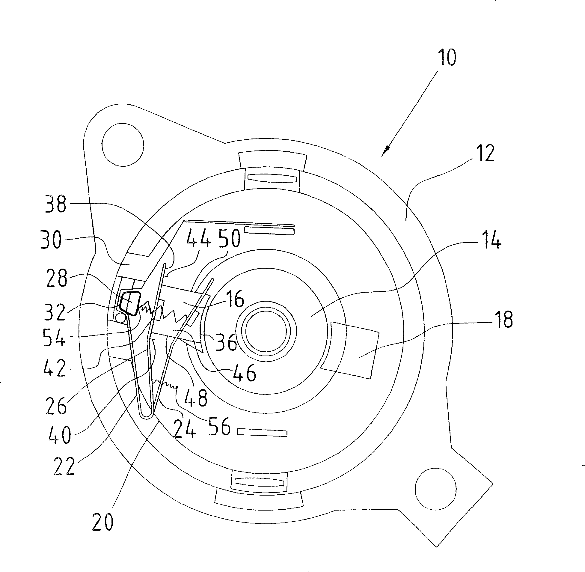
[0029] figure 1 A schematic diagram of a universal electric machine 10 is shown, which is intended, for example, for machine tools or domestic appliances, which are operated, for example, with a power of up to 2000 watts or 2500 watts.

[0030] The universal electric machine 10 comprises a housing 12 and an electric machine accommodated in this housing with a commutator 14 , against which carbon brushes 16 , 18 abut under force in order to transmit current. For this purpose, the carbon brushes 16 , 18 each protrude from a holding device (carbon brush holder) which is purely indicated in combination with the carbon brush 16 and is in the form of a known leaf spring 20 (carbon brush holder), which includes a holding leg Or holding part 22 and a carrier part 24 for receiving carbon brush 16 . The retaining portion 22 can be fixed between the support and the opposing support 26, 28, 30 in a known manner. For this reason, holding part 22 has in this embodiment a cross-section tha...


PUM


Abstract

The invention relates to a device for guiding or holding a carbon brush (16, 18) and exerting a force in a direction towards a current carrying element such as a commutator (14), comprising a The first spring element (20) on the side. In order for the carbon brush to be pressed against the commutator with the necessary pressure, the invention proposes to act on the first spring element (20) with a direction towards the commutator (14) of the carbon brush (16, 18) Second spring element applying force.

Description

technical field [0001] The invention relates to a device for holding or guiding a carbon brush and for exerting a force on the carbon brush in the direction towards a current carrying element such as a commutator or a slip ring, the device comprising a device acting on the side of the carbon brush facing away from the working surface The leaf spring element is used as the first spring element, which is connected to the carbon brush or a part connected to the carbon brush in a materially bonded manner. Background technique [0002] A corresponding device has been disclosed in DE-A-10207406 (WO-A-03 / 071662), where carbon brushes protrude from curved leaf spring elements with load-bearing parts, carbon brushes The back of the back rests flat on the load-bearing part and is welded. [0003] Furthermore, according to DE-C-10063405, the carbon brush rests against the leaf spring part and is fixed by freely cut webs. [0004] In this known arrangement, the leaf spring performs mu...

Claims


Application Information

Patent Timeline
Patent Type & Authority Patents(China)
IPC IPC(8): H01R39/38H01R39/39
Inventor G·G·尤伊克W·凯斯多夫
Owner SCHUNK KOHLENSTEOFFTECHNIK GMBH
Why Eureka
Try Eureka