A minimally-invasive, laterovertically expanding, intervertebral disc scaffolding

a scaffolding and intervertebral disc technology, applied in the field of intervertebral disc scaffoldings, can solve the problems of increasing the stress on the annulus, increasing the risk of delamination and damage on the annulus, and affecting the function of the intervertebral disc, so as to facilitate the addition of grafting material, and maximize the contact area

Inactive Publication Date: 2014-02-06
SPIDER TEK
View PDF0 Cites 36 Cited by
  • Summary
  • Abstract
  • Description
  • Claims
  • Application Information

AI Technical Summary

Benefits of technology

[0012]In some embodiments, the expansion mechanism can laterally expand at least a portion of the second support and at least a portion of the first support away from each other, the laterally expanding including a rotation at a point of intersection between the first support and the second support, such that the laterally expanding includes a scissor-like movement between the first support and the second support in the intervertebral space; and, the vertically expanding includes expanding at least a portion of the first support or at least a portion of the second support for a distraction of the intervertebral space, the vertically expanding includes introducing a vertical expansion member into the intervertebral space through the single point of entry and into the first support or the second support of the scaffolding to provide a vertical force on adjacent vertebral endplates for the distraction of the intervertebral space. In these embodiments, the collapsed configuration is configured for the low profile entry through the annulus fibrosis, having the shape of an I for inserting the scaffolding into the intervertebral space through the single point of entry; and, the expanded configuration is configured to provide a stable support for fusing the intervertebral space, having the shape of an X in the intervertebral space, the point of intersection biased anteriorly in the intervertebral space to facilitate the adding of a grafting material and maximize an area of contact between the scaffolding, the grafting material, and the vertebral endplates of the intervertebral space.
[0013]It should be appreciated that the collapsed configuration of the scaffolding can be any configuration that will facilitate obtaining the functions taught herein. In some embodiments, the collapsed configuration has the shape of an I for the inserting of the scaffolding into the intervertebral space, and the expanded configuration has the shape of an X in the intervertebral space. In some embodiments, the shape of the X is asymmetrical in the intervertebral space and the intersection is biased anteriorly in the intervertebral space to facilitate the adding of the grafting material and maximize an area of contact between the scaffolding, the grafting material, and the vertebral endplates of the intervertebral space. For example, the low profile entry of the scaffolding in the collapsed configuration contributes to the minimally-invasive nature of the treatments taught herein, and any low profile entry that accomplishes the reduction of trauma sought herein can be used. In some embodiments, the low profile entry has an area with an effective diameter ranging from about 5 mm to about 12 mm for a minimally-invasive single point of entry through the annulus fibrosis.

Problems solved by technology

Intervertebral disc disease is a major worldwide health problem.
Loss of water binding by the nucleus results in more compressive loading of the annulus.
This renders the annulus more susceptible to delamination and damage.
Damage to the annulus, in turn, accelerates disc degeneration and degeneration of surrounding tissues such as the facet joints.
These procedures only address the symptom of lower back pain, nerve compression, instability and deformity.
However this makes it difficult to insert and position properly.
However, such cage have the typical limitation in that it is not symmetrical about the sagittal plane if it is loaded from one side in a common approach called the Transforaminal Lumbar Interbody Fusion (TLIF), it does not provide a path for bone graft to be insertion to fill in the space surrounding the cage, it does not conform to the nonplanar surface of the endplate, and it cannot expand laterally to increase the footprint relative to size of the insertion.
The last limitation requires that it be inserted through a large opening through the body tissues to accommodate a large enough cage for stability, and this large opening necessitates more trauma for the patient.

Method used


Image

  • A minimally-invasive, laterovertically expanding, intervertebral disc scaffolding
  • A minimally-invasive, laterovertically expanding, intervertebral disc scaffolding
  • A minimally-invasive, laterovertically expanding, intervertebral disc scaffolding

Examples


Embodiment Construction

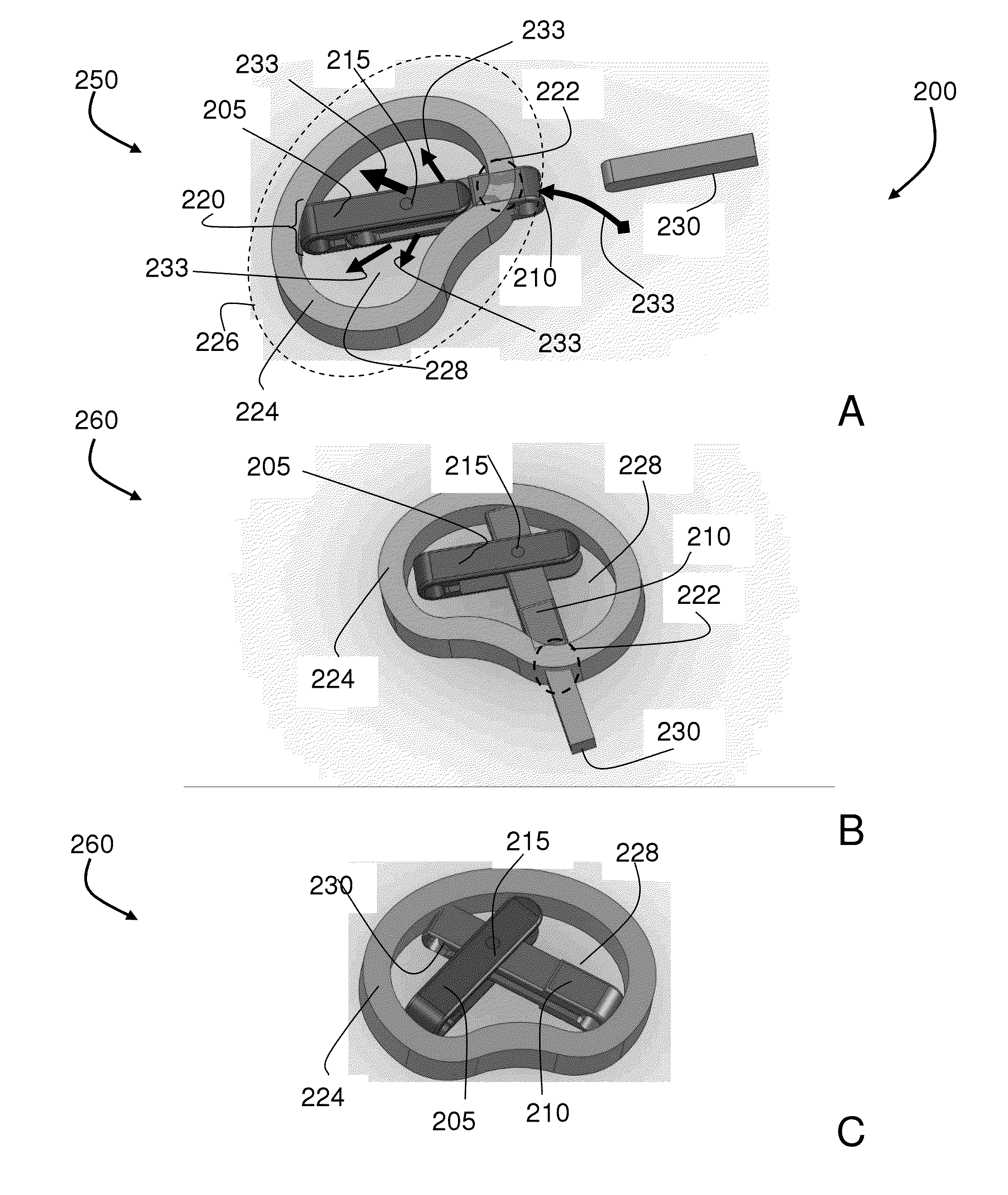
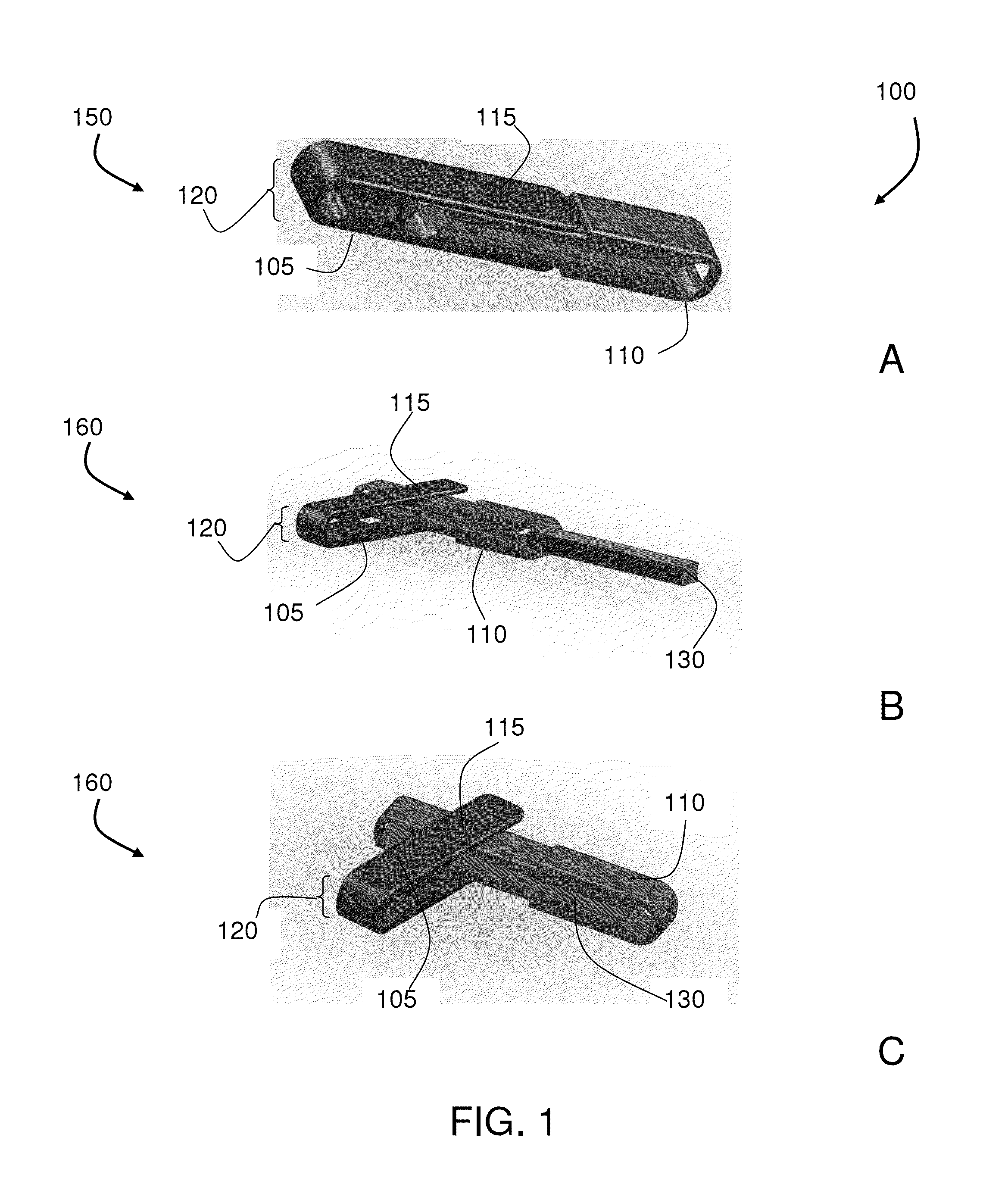
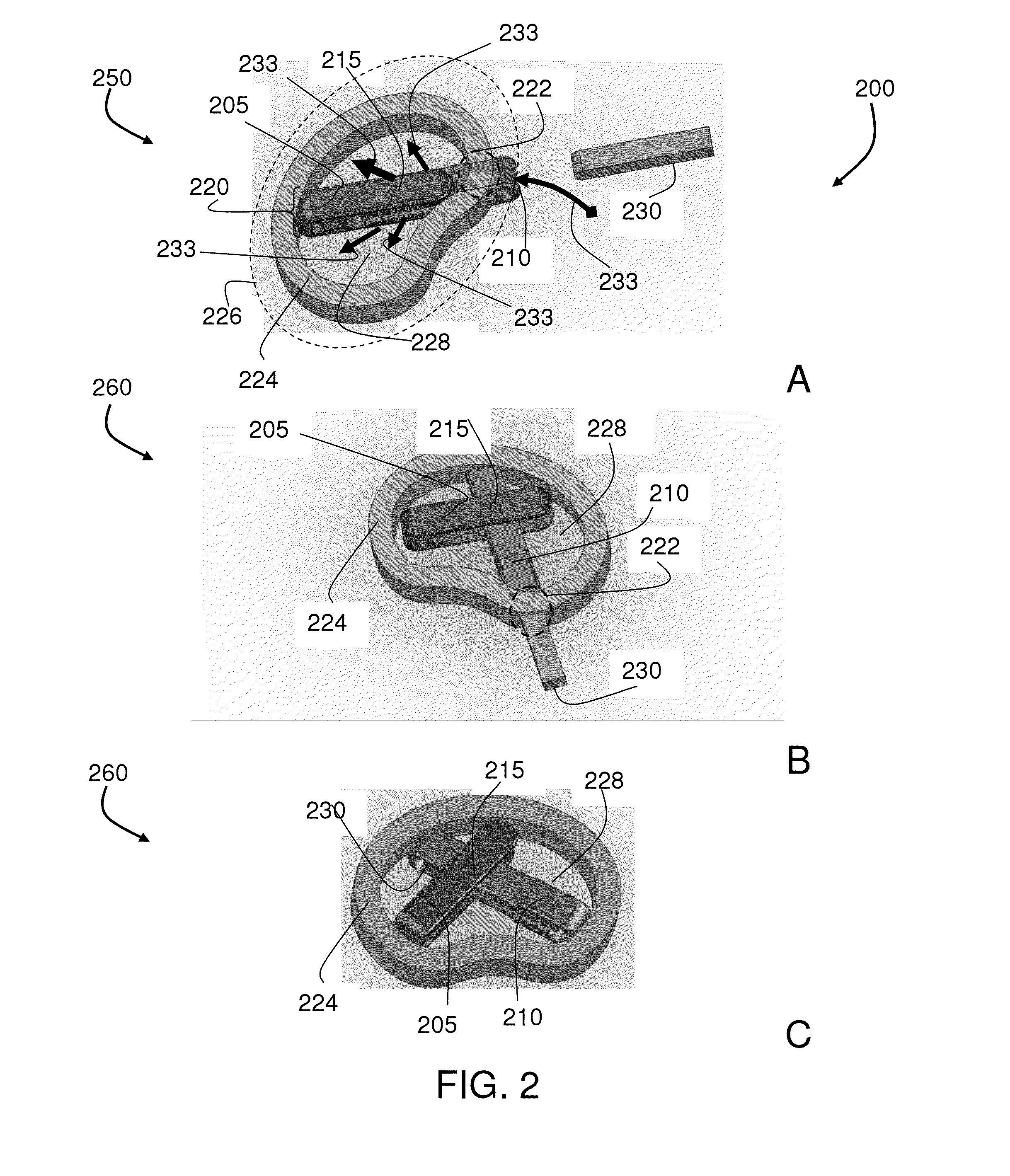
[0022]The teachings provided herein are generally directed to a method of fusing an intervertebral space in a subject using a laterovertically-expandable scaffolding. For example, the scaffolding can include two elongated segments connected by a hinge, such that the elongated segments can act as support members, or beams, in some embodiments, within an intervertebral disc that has had the nucleus pulposus removed.

[0023]The elongated segments can collapse into each other, much like the components of a jackknife collapse into each other, for example, in at least substantially collinear fashion. The elongated segments can rotate such that they cross, and they can connect in such a way that a component for adding a vertical force between vertebrae can be positioned within at least one of the segments. In some embodiments, one of the segments can have a slot that allows for insertion of an expansion mechanism. A shim or other graft material are examples of an expansion mechanism that can...


PUM


Abstract

A laterovertically expandable scaffolding is provided for supporting an intervertebral disc space using a minimally invasive procedure. The scaffolding can be configured to provide a low-profile entry in a collapsed configuration through the single point of entry through the annulus. The expanding including laterally expanding at least a portion of a first support and at least a portion of a second support away from each other; and, vertically expanding at least a portion of the first support or at least a portion of the second support for a distraction of the intervertebral space. The lateral movement can include a rotation at a point of intersection between the first support and the second support, the intersection being biased anteriorly in the intevertebral space to facilitate the adding of the grafting material.

Description

CROSS-REFERENCE TO RELATED APPLICATIONS[0001]This application claims the benefit of U.S. Provisional Application No. 61 / 678,070, filed Jul. 31, 2012, which is hereby incorporated herein by reference in its entirety.BACKGROUND[0002]1. Field of the Invention[0003]The teachings herein are directed to intervertebral scaffoldings and methods of creating the same.[0004]2. Description of the Related Art[0005]Intervertebral disc disease is a major worldwide health problem. In the United States alone almost 700,000 spine procedures are performed each year and the total cost of treatment of back pain exceeds $30 billion. Age related changes in the disc include diminished water content in the nucleus and increased collagen content by the 4.sup.th decade of life. Loss of water binding by the nucleus results in more compressive loading of the annulus. This renders the annulus more susceptible to delamination and damage. Damage to the annulus, in turn, accelerates disc degeneration and degenerati...

Claims


Application Information

Patent Timeline
Patent Type & Authority Applications(United States)
IPC IPC(8): A61F2/44A61F2/46
CPCA61F2/4601A61F2/4455A61F2/4684A61F2002/2835A61F2002/30471A61F2002/30556A61F2002/30579
Inventor TO, JOHNFLYNN, JOHN J.BIRKMEYER, PAUL J.
Owner SPIDER TEK
Why Eureka
Try Eureka