Mobile image apparatus and an antenna apparatus used for the mobile image apparatus

a mobile image and antenna technology, applied in the direction of separate antenna unit combinations, resonant antennas, radiating element structural forms, etc., can solve the problems of dangerous and difficult use of mobile image apparatus

Inactive Publication Date: 2000-02-22
MURATA MFG CO LTD
View PDF12 Cites 18 Cited by
  • Summary
  • Abstract
  • Description
  • Claims
  • Application Information

AI Technical Summary

Benefits of technology

According to the above described mobile image apparatus, an extra antenna is connected to the power feeding terminal or the free terminal of one of the chip antennas, thereby easily increasing the lengths if the conductors provided for the antennas. It is thus possible to receive with high sensitivity a lower frequency band in which a longer conductor is required
Since the trimming electrode is coated with a resin layer, the environment-resistance and characteristics are improved and further the reliability of the chip antenna is enhanced.

Problems solved by technology

However, the above known type of mobile image apparatus presents the following problem.
Thus, the mobile image apparatus is dangerous and difficult to use.

Method used


Image

  • Mobile image apparatus and an antenna apparatus used for the mobile image apparatus
  • Mobile image apparatus and an antenna apparatus used for the mobile image apparatus
  • Mobile image apparatus and an antenna apparatus used for the mobile image apparatus

Examples


first embodiment

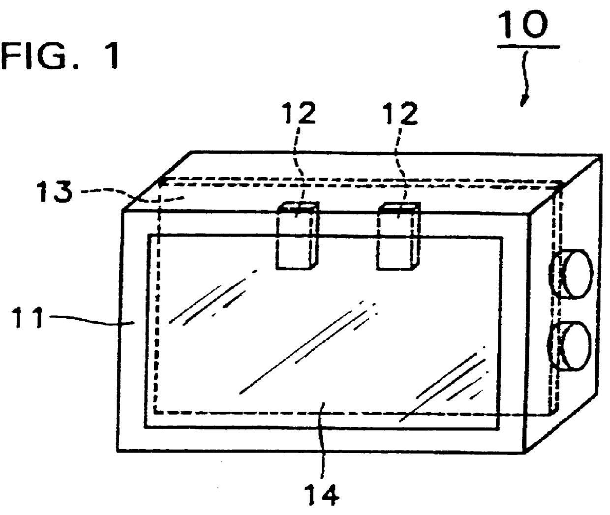
FIG. 1 is a perspective view illustrating a mobile image apparatus of the present invention. A mobile image apparatus 10 is formed of a case unit 11, chip antennas 12, 12 built into the case unit 11, a mounting board 13 on which the chip antennas 12, 12 are mounted, and an image display unit 14 for displaying radio waves carried on the chip antennas 12, 12 as an image. It should be noted that the circuit on the mounting board is not shown in FIG. 1.

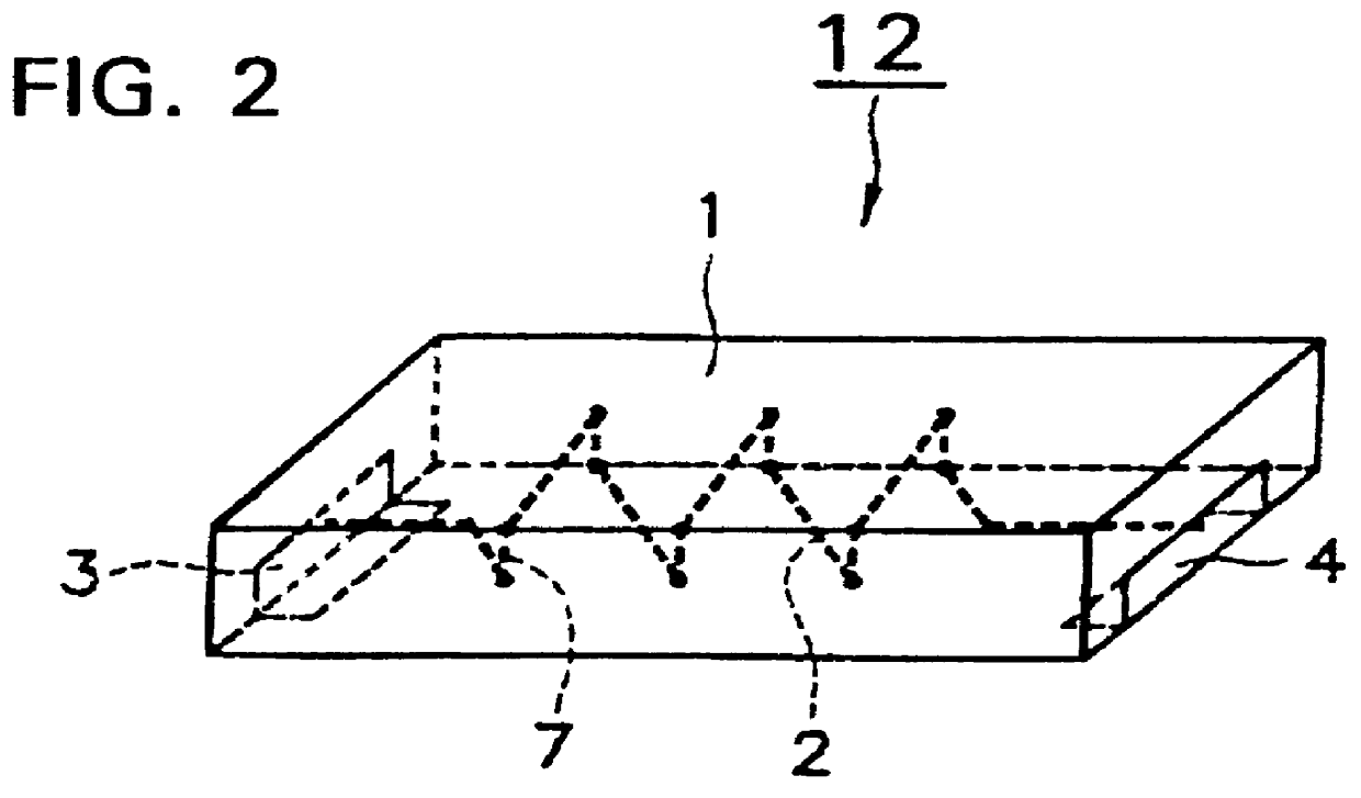
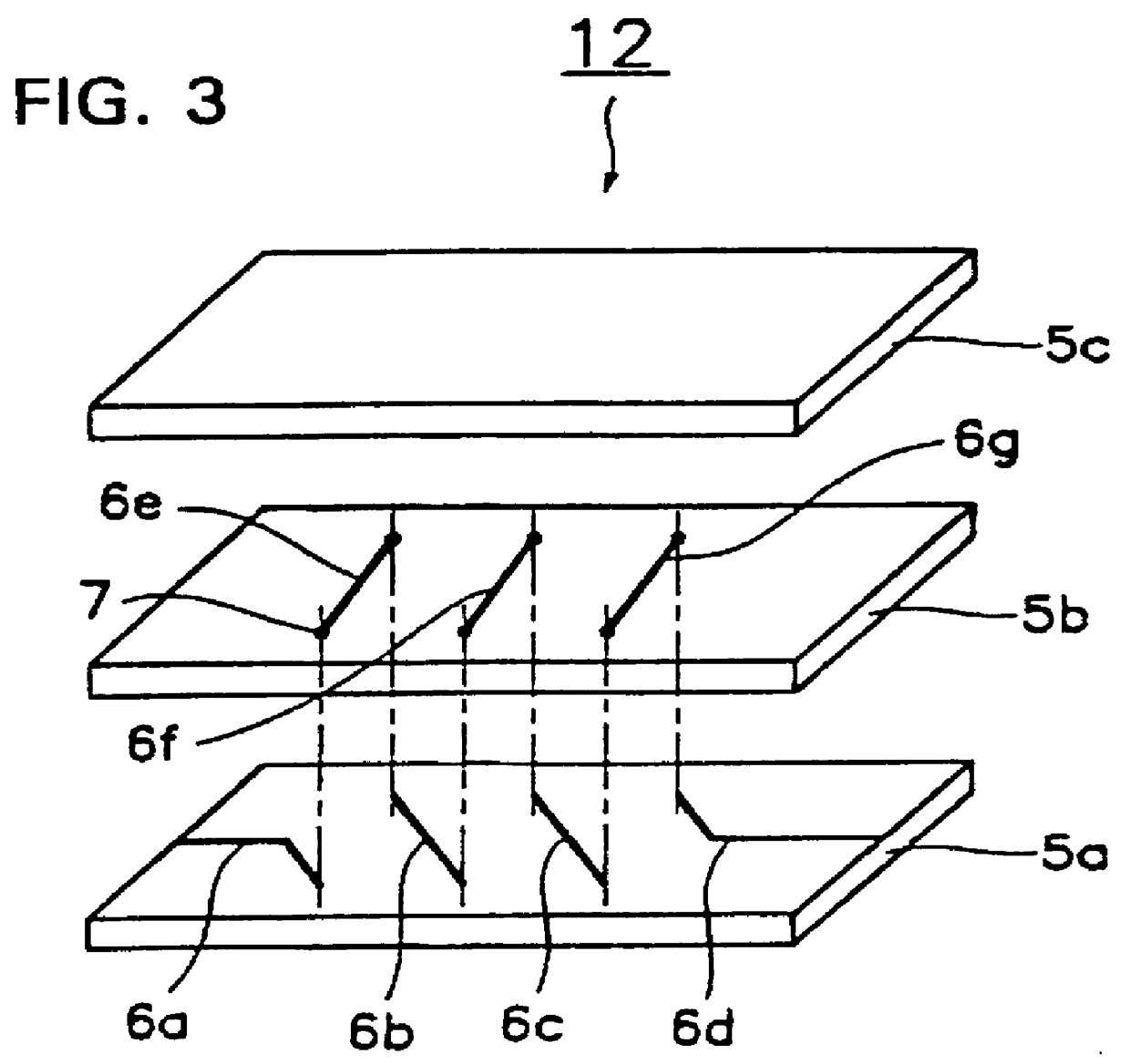
FIGS. 2 and 3 are respectively a perspective view and an exploded perspective view of the chip antenna shown in FIG. 1. The chip antenna 12 has a conductor 2, a power feeding terminal 3, and a free terminal 4. The conductor 2 is spirally wound within a rectangular-prism substrate 1 in the longitudinal direction of the substrate 1. The power feeding terminal 3 is formed over surfaces of the substrate 1 in order to apply a voltage to the conductor 2 and is connected to one end of the conductor 2. The free terminal 4 is connected to the othe...

second embodiment

According to the mobile image apparatus of the above-described second embodiment, two chip antennas are connected in series to each other, thereby easily increasing the lengths of the conductors. It is thus possible to perform the receiving operation with high sensitivity even in the VHF band, in other words, in a lower frequency band in which a longer conductor is required.

The VHF band having a center frequency of 150 MHz was received by using chip antennas having dimensions of 8 mm.times.5 mm.times.2 mm connected in series to each other and by using a conventionally used rod antenna having a length of 75 cm. Moreover, the UHF band having a center frequency of 800 MHz was received by using one chip antenna having dimensions of 8 mm.times.5 mm.times.2 mm and by using a conventionally used rod antenna having a length of 75 cm. The above-described examples show that there was very little difference in the gain in all the channels between this embodiment and known mobile image apparatu...

third embodiment

FIGS. 8 and 9 are respectively a perspective view and an exploded perspective view illustrating a chip antenna of the present invention. A chip antenna 510 is formed of a rectangular-prism substrate 51l having a mounting surface 611, a conductor 512, a power feeding terminal 513, and a trimming electrode 514 formed generally in the shape of a rectangle and provided on the surface of the substrate 511. The conductor 512 is spirally wound within the substrate 511, the winding axis C being positioned in the direction parallel to the mounting surface 611, i.e., in the longitudinal direction of the substrate 511. The power feeding terminal 513 is formed over surfaces of the substrate 511 in order to apply a voltage to the conductor 512. The conductor 512 is connected at one end to the power feeding terminal 513 and at the other end to the trimming electrode 514. With this configuration, a capacitive coupling is generated between the trimming electrode 514 and a ground (not shown) of a mo...


PUM


Abstract

The invention provides a mobile image apparatus (10), comprising: a case unit (11); at least one antenna (12) disposed at least one of within said case unit (11) and outside said case unit (11); wherein said chip antenna (12) comprises; a substrate (1) made of at least one of a dielectric material and a magnetic material; at least one conductor (2) disposed at least one of within said substrate (1) and on a surface of said substrate (1); at least one power feeding terminal (3) disposed on a surface of said substrate (1) and connected to one end of said conductor (2) for applying a voltage to said conductor (2).

Description

1. Field of the InventionThe present invention relates to a mobile image apparatus such as a liquid-crystal television and a portable video apparatus, and more particularly, to a mobile image apparatus having an antenna disposed at least one of within said case unit and outside said case unit. The present invention also relates to an antenna apparatus associated with the above described mobile image apparatus.2. Related Art of the InventionFIG. 28 illustrates a conventional mobile image apparatus. A mobile image apparatus 450 has a case unit 451, an antenna 452 connected to the case unit 451, and an image display unit 453 for displaying radio waves carried on the antenna 452 as a video image.Generally, the antenna 452 is an elastic monopole antenna, and is formed by, as shown in FIG. 29, mounting a radiation device 455 having a length of 1 / 4 .lambda. (.lambda.: the wavelength at a resonant frequency) on a ground, for example, a case unit. One end of the radiation device 455 serves a...

Claims


Application Information

Patent Timeline
Patent Type & Authority Patents(United States)
IPC IPC(8): H01Q1/36H01Q1/38H01Q1/22H01Q21/30
CPCH01Q1/22H01Q1/2283H01Q1/36H01Q1/362H01Q1/38H01Q21/30
Inventor MANDAI, HARUFUMITSURU, TERUHISAOIDA, TOSHIFUMI
Owner MURATA MFG CO LTD
Why Eureka
Try Eureka