Method of implanting a uni-condylar knee prosthesis

a knee prosthesis and unicondylar technology, applied in the field of knee surgery, can solve the problem that the component may have a tendency to sink into the soft bone, and achieve the effect of improving the stability and stability of the knee join

Inactive Publication Date: 2000-05-09
BIOMET MFG CORP
View PDF46 Cites 235 Cited by
  • Summary
  • Abstract
  • Description
  • Claims
  • Application Information

AI Technical Summary

Benefits of technology

The steps of the method are to provide a femoral component having an articulating surface and a bone mating surface; providing a tibial component having a first surface operable to engage said femoral articulating surface, a bone mating surface opposite said first surface, a first edge and a second edge, said bone mating surface sloping from said first edge to said second edge and a post extending from the bone mating surface. Further steps include making at least one cut on the femur to accommodate the bone mating surface on the femoral component; making a cut on the tibia that slopes down along a line drawn from the midline to the outer edge of the tibia following the sclerotic bone formation. The method further includes the steps of forming at least one hole on the cut of the tibia that the post may extend into to align the tibial component on the tibia; and implanting the femoral and the tibial component onto the cut femur and the cut tibia. The method further comprises making a distal femoral cut on the femur. The method also comprises cementing the component.

Problems solved by technology

If the surgeon does not get the tibial component properly aligned and out to the hard cortical bone, the component may have a tendency to sink into the softer bone in the center region of the tibia plateau.

Method used


Image

  • Method of implanting a uni-condylar knee prosthesis
  • Method of implanting a uni-condylar knee prosthesis
  • Method of implanting a uni-condylar knee prosthesis

Examples


Embodiment Construction

The preferred embodiment herein described is not intended to be exhaustive or to limit the invention to the precise form disclosed. This description is limited to the preferred embodiment only and is intended to describe the invention to enable one of ordinary skill in the art to practice the invention.

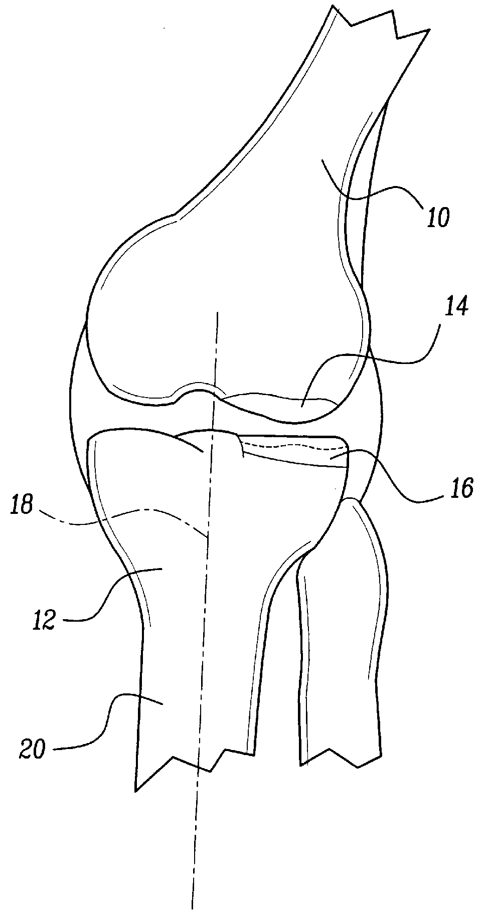
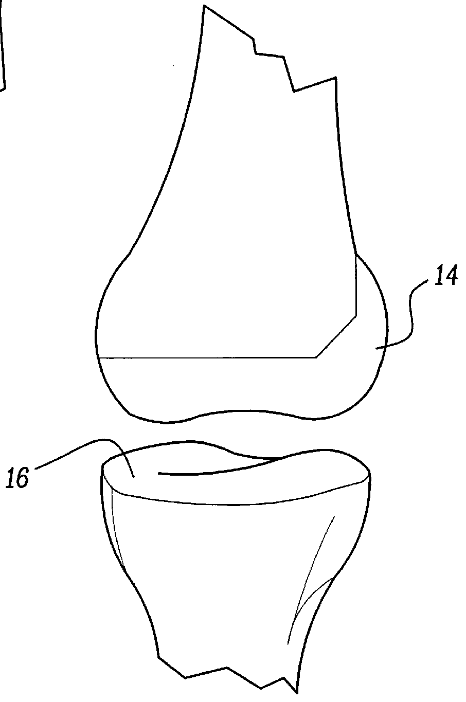
Referring now to FIGS. 1 and 2, a uni-condylar knee prosthesis implanted using the method of the invention is shown. The femur 10 is shown in combination with a tibia 12. The femur 10 has a femoral component 14 implanted therein. The tibia has a tibial component 16 implanted therein. While a left lateral surgery is shown, it is known that the method will apply to both medial and lateral components, as well as left and right knees. A midline 18 is shown on the tibia 12 that extends along the shaft 20 of the tibia 12.

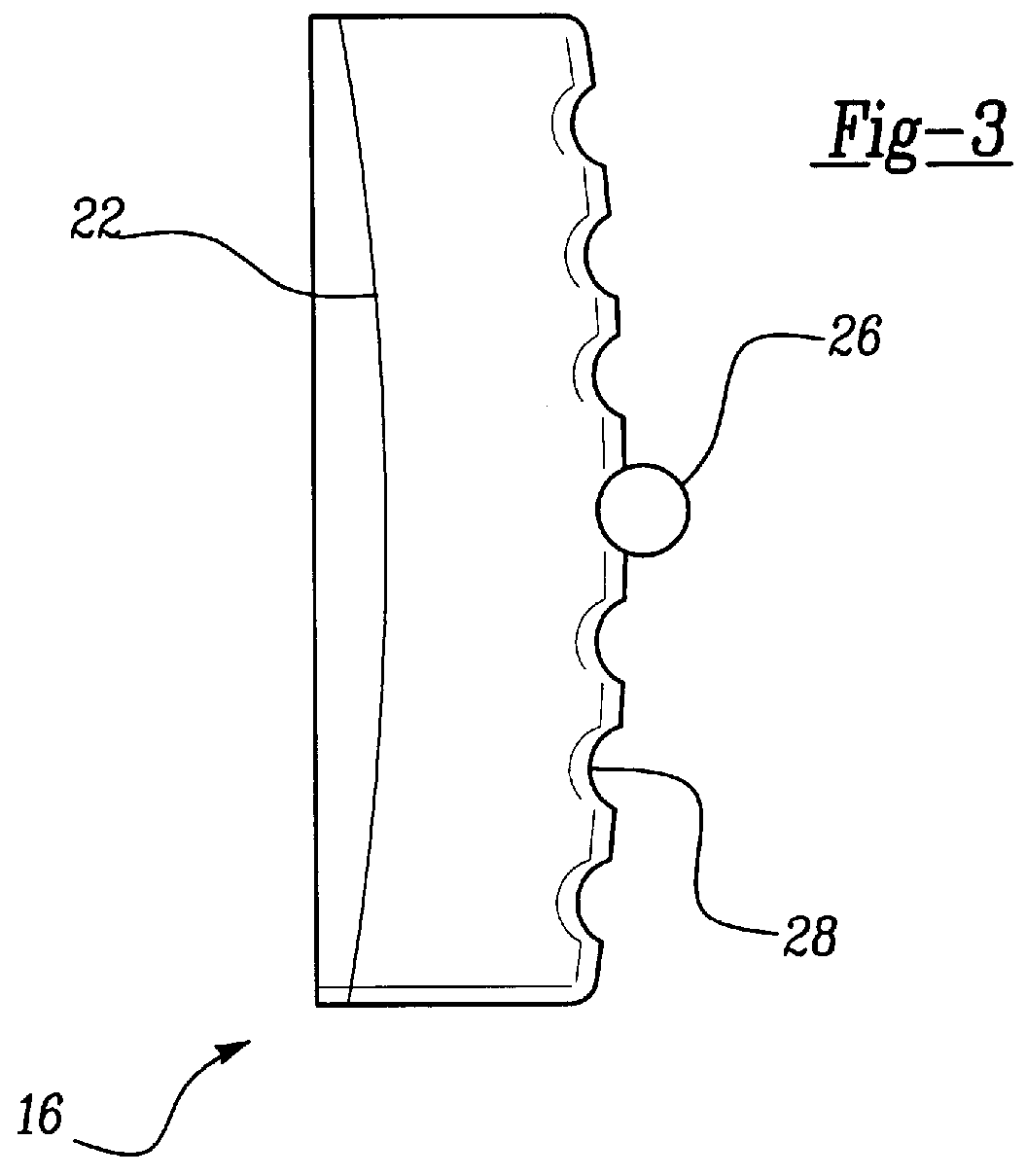
Referring now to FIG. 3, the tibial component 16 is shown in detail. The tibial component 16 has an upper articulating surface 22 that engages femoral component 14. The top...


PUM


Abstract

The invention relates generally to a method for implanting a uni-condylar knee prosthesis. The method includes steps for preparing the bone surfaces of both the femoral and tibial effected compartments. The femoral compartment is prepared by making a distal cut, a posterior cuts and a posterior chamfer cut. Holes that correspond to posts on the femoral component are also prepared. The tibial compartment is prepared using a cutting guide and following the sclerotic bone formation on the proximal tibia. At least one hole is prepared in the sloped cut tibial surface to use for alignment when cementing the tibial component that has an alignment peg.

Description

BACKGROUND OF THE INVENTION1. Field of the InventionThe invention relates generally to a method for knee surgery, and more specifically, to a method for implanting a uni-condylar knee prosthesis.2. Discussion of the Related ArtIt is well known to perform surgery on a knee having arthritis or other bone degenerating diseases and to resurface the articulating junctions with a prosthetic device. One such method is to resurface only the portion of the knee joint that is effected using a uni-condylar knee prosthesis. One such device is shown in U.S. Pat. No. 3,852,830 to Marmor. Marmor teaches a uni-condylar femoral component and tibial component. The femoral component is thin and the bone is prepared using a bur. The tibial component has a generally flat distal surface and a horizontal cut on the tibia that is below the level of the defect. In fact, many other patents demonstrate a uni-condylar reconstruction surgery such as the patents shown in Table 1._________________________________...

Claims


Application Information

Patent Timeline
Patent Type & Authority Patents(United States)
IPC IPC(8): A61B17/14A61B17/16A61B17/15A61B17/17A61F2/38
CPCA61B17/154A61F2/38A61B17/1764A61B17/155A61B17/157Y10S623/908A61F2002/3895
Inventor BRASLOW, JONATHON S.KING, JEFFREY
Owner BIOMET MFG CORP
Why Eureka
Try Eureka