Energy supplying system

a technology of energy supply and system, applied in the direction of machine/engine, process and machine control, electric generator control, etc., can solve the problems of complex system and hardly anticipated

Inactive Publication Date: 2000-12-12
HONDA MOTOR CO LTD
View PDF17 Cites 20 Cited by
  • Summary
  • Abstract
  • Description
  • Claims
  • Application Information

AI Technical Summary

Problems solved by technology

However, the heat emitted from the solar cells also depends on the local climate similar to the electric power from the cells and will hardly be anticipated for constant and stable emission which may be expected in a generator using fossil fuel.
Because the cooling water is heated up only to a unsatisfactory temperature and has to be subjected to adiabatic compression to have a desired higher temperature before it is used, the system will be complicated.

Method used


Image

  • Energy supplying system
  • Energy supplying system
  • Energy supplying system

Examples


Embodiment Construction

.

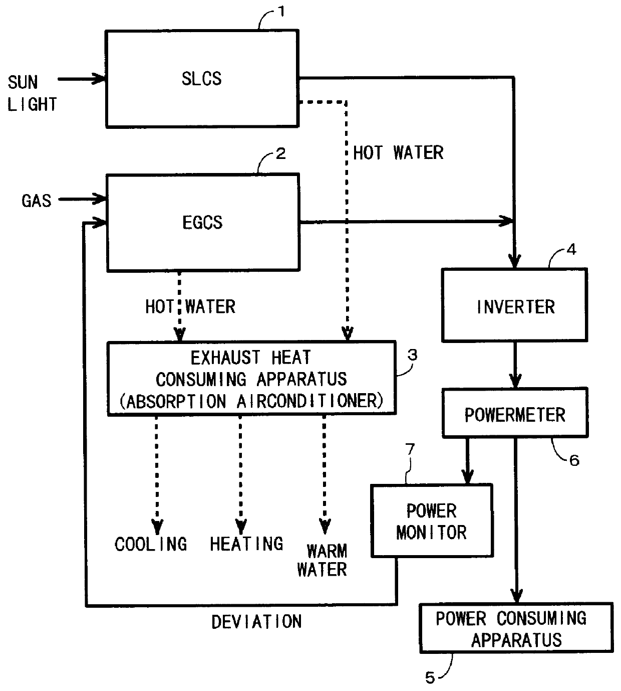
The present invention will be described in more detail referring to the accompanying drawings. FIG. 1 is a schematic diagram of an energy supplying system according to an embodiment of the present invention. As shown, the energy supplying system includes an SLCS (sunlight cogeneration system) 1 and an EGCS (engine generator cogeneration system) 2. The SLCS 1 and the EGCS 2 will be explained later in more detail. Hot water yielded in the SLCS 1 and the EGCS 2 is transferred to a waste (or exhaust) heat consuming apparatus 3. It is assumed for ease of the description that the waste heat consuming apparatus 3 is an absorption refrigerator or an absorption airconditioner.

After the hot water is declined in temperature by the absorption airconditioner 3, it is circulated back to the SLCS 1 and the EGCS 2. The absorption airconditioner will also be explained later in more detail.

The SLCS 1 and the EGCS 2 generate an electric power which is transmitted to an inverter 4 where it is converte...


PUM

PropertyMeasurementUnit
temperatureaaaaaaaaaa
energyaaaaaaaaaa
poweraaaaaaaaaa

Abstract

Energy supplying system in which effective use of waste heat from a solar power generator and an engine power generator. Electric power generated by an SLCS (sunlight cogeneration system) 1 and an EGCS (engine cogeneration system) 2 is supplied to a power consuming apparatus while its relevant waste or exhausted heat is transferred to a heat consuming apparatus 3. The power generated by the SLCS 1 varies depending on the local climate and is monitored with a power meter 6 or a power monitor apparatus 7. When the power from the SLCS 1 is declined, it is compensated by increasing the power output of the EGCS 2. Since the total power generated by the SLCS 1 and the EGCS 2 is maintained constant and the total waste heat released from the SLCS1 and the EGCS 2 is relatively stable, the heat consuming apparatus 3 as well as an power consuming apparatus 5 are steadily energized.

Description

1. Field of the InventionThe present invention relates to an energy supplying system for use of solar energy and particularly, to an energy supplying system for supplying one or more energy consuming apparatus with energy generated by different types of energy generating facilities.2. Description of the Related ArtCogeneration systems are well known in which electric power is generated by an internal combustion engine fueled with fossil fuel and heat generated at the time by the internal combustion engine is transferred to a heat exchanger for potential use as energy.The use of solar energy also has been focused and, for example, a power supplying system built by a combination of a cogeneration system, a solar generator, and a commercial power source is disclosed in Japanese Patent Laid-open Publication (Hei) 8-186935 in which the power supplying system can supply a desired electric power from the different sources with balance while offsetting the drawback of solar power generation...

Claims


Application Information

Patent Timeline
Patent Type & Authority Patents(United States)
IPC IPC(8): F03G6/00F02G5/02F02G5/00F02C6/18H01L31/04G05F1/67H01M8/00H02J3/38H02N6/00H02P9/04
CPCF02C6/18F02G5/02F03G6/00F03G6/001Y02T10/166Y02E10/46Y02E10/52Y02E20/14Y02P80/15Y02T10/12
Inventor KOMURA, NORIO
Owner HONDA MOTOR CO LTD
Why Eureka
Try Eureka