Device for monitoring the intake subassembly of an agricultural harvesting machine

a harvesting machine and sub-assembly technology, applied in the field of agricultural harvesting machines having intake mechanisms, can solve the problem that the monitoring device may generate a fault warning and other problems

Inactive Publication Date: 2001-11-20
CLAAS SAULGAU
View PDF24 Cites 35 Cited by
  • Summary
  • Abstract
  • Description
  • Claims
  • Application Information

AI Technical Summary

Benefits of technology

A further advantage is that existing machines can be retrofitted with a monitoring device and sensor, according to the invention.
The monitoring system may be designed such that an electrical signal is produced thereby, for moving the cut-out clutch into its blocking position, if a rotational movement of an intake subassembly component or a transmission member being monitored by the activated sensor is detected. The sensor may be associated wit...

Problems solved by technology

The monitoring device may then generate a fault warning if a certain reduction in rotational spee...

Method used


Image

  • Device for monitoring the intake subassembly of an agricultural harvesting machine
  • Device for monitoring the intake subassembly of an agricultural harvesting machine
  • Device for monitoring the intake subassembly of an agricultural harvesting machine

Examples


Embodiment Construction

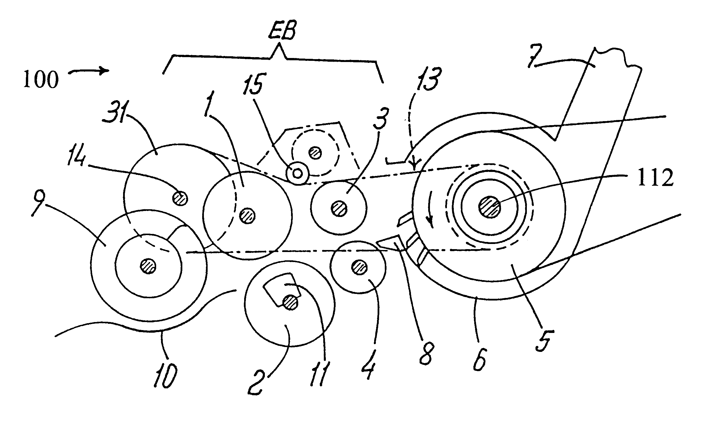
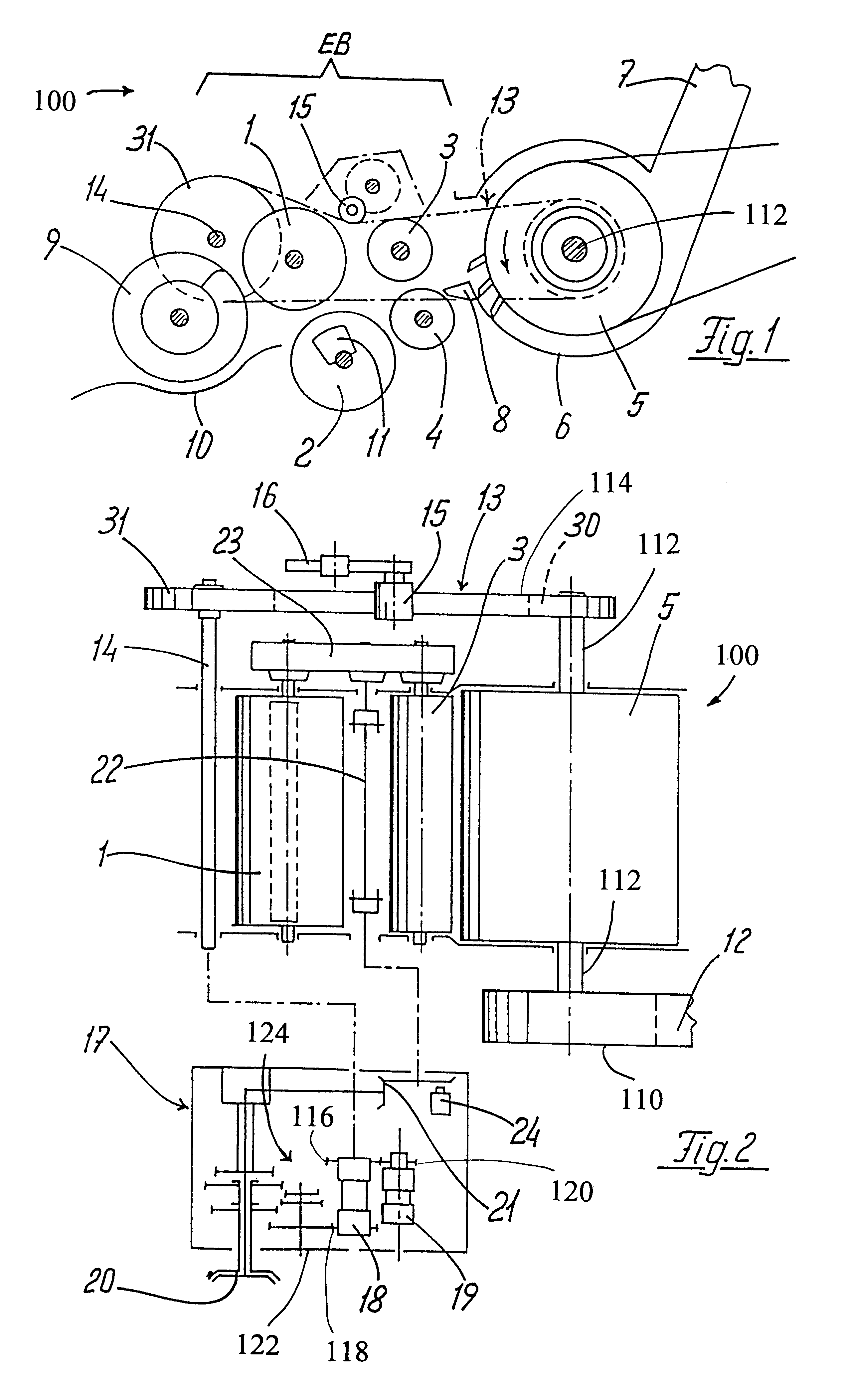
An intake subassembly 100 is shown in FIGS. 1 and 2. The remaining structure of the complete forage harvester, not shown, may be of conventional design. The intake subassembly 100 is equipped with two, parallel-axis feed rollers 1 and 2, and two following parallel-axis compression rollers 3, 4. The rotatable cutting cylinder 5, which is driven counter clockwise as seen in the illustration of FIG. 1, is arranged immediately behind the compression rollers 3, 4 in the direction of movement of the foraged crop. The cutting cylinder 5 is rotatably mounted in a cylinder housing 6, which may also be of conventional design. The rising conveyor shaft 7 for the foraged crop is attached to the cylinder housing 6. The fixed shear bar 8 is located between the compression rollers 3, 4 and the cutting cylinder 5 as shown. Two opposed cross augers 9, for supplying the material being foraged to the feed rollers 1, 2, are laterally disposed in front of the feed rollers 1, 2. A tray 10 is arranged bel...


PUM


Abstract

An intake subassembly for an agricultural harvesting machine, in particular a self-propelled forage harvester for corn, grass and the like, including a cutting cylinder, feed rollers, and compression rollers, has a cut-out clutch for bringing the feed rollers and the compression rollers to a sudden stop. The machine may have a monitor system for detecting and processing information relating to the status and motion of the components of the subassembly and generating a signal to interrupt and brake the detected motion, for example, in response to the presence of foreign objects or overloads in the subassembly.

Description

FIELD OF THE INVENTIONThe invention relates to agricultural harvesting machines having intake mechanisms, in particular, silage cutters or forage harvesters for corn, grass and the like, comprising a cutting cylinder mounted in a cylinder housing and rotatably driven by the main drive unit in the machine.BACKGROUND OF THE INVENTIONApplicant is aware of U.S. Pat. Nos. 4,275,546; 4,286,424; 4,306,403; 4,496,105; 4,720,963; 4,776,154; 5,558,163; 5,592,029; 5,819;512 and. 5,921,071, the disclosures of which are incorporated by reference herein.In machines of conventional design, the cutting cylinder typically has a switchable drive element connected thereto, and a drive train, for driving the rollers of an intake subassembly equipped with a foreign body detecting device. A reversing transmission unit for driving the intake subassembly in the reverse direction, and a cut-out clutch for bringing the intake subassembly to a sudden halt are mounted in the drive train. The cut-out clutch is ...

Claims


Application Information

Patent Timeline
IPC IPC(8): A01D41/00A01D41/127A01F29/16A01F29/00A01D41/12
CPCA01D41/1274A01F29/16Y10S56/06
Inventor RAUCH, HANSPOLLKLAS, MANFRED
Owner CLAAS SAULGAU
Why Eureka
Try Eureka