Instrument for placing surgical clips

Inactive Publication Date: 2005-01-04
AESCULAP AG
View PDF6 Cites 247 Cited by
  • Summary
  • Abstract
  • Description
  • Claims
  • Application Information

AI Technical Summary

Benefits of technology

is to construct a placing instrument of the kind in the preamble in such a way that the large amount of force necess

Problems solved by technology

By this embodiment it is possible to also use feeding plates which consist of very thin materials and therefore are

Method used


Image

  • Instrument for placing surgical clips
  • Instrument for placing surgical clips
  • Instrument for placing surgical clips

Examples


Embodiment Construction

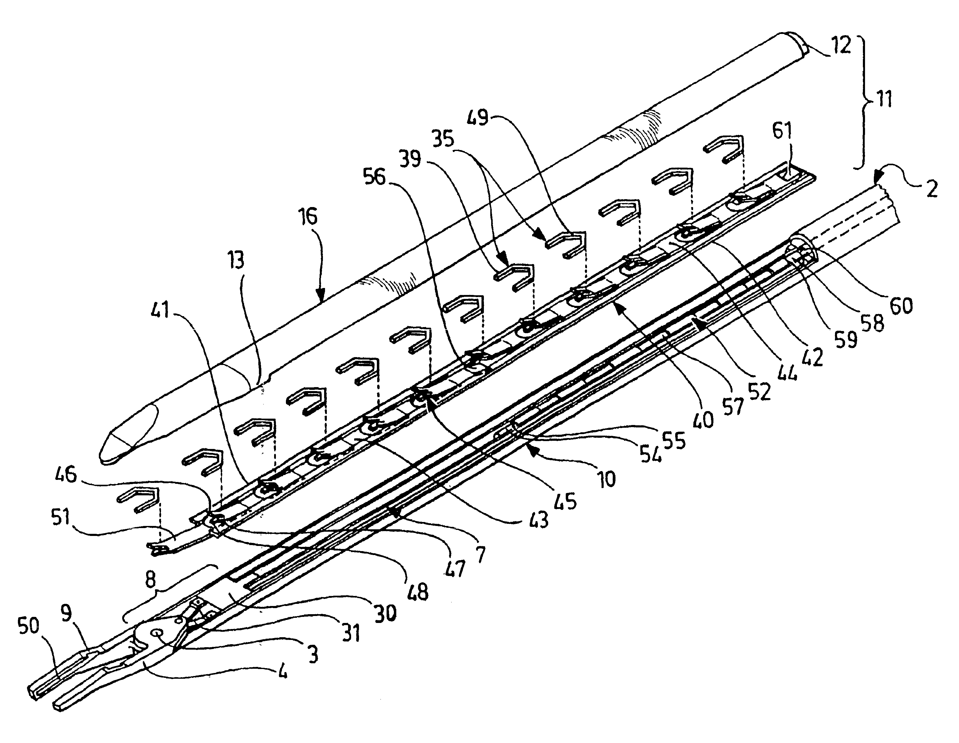
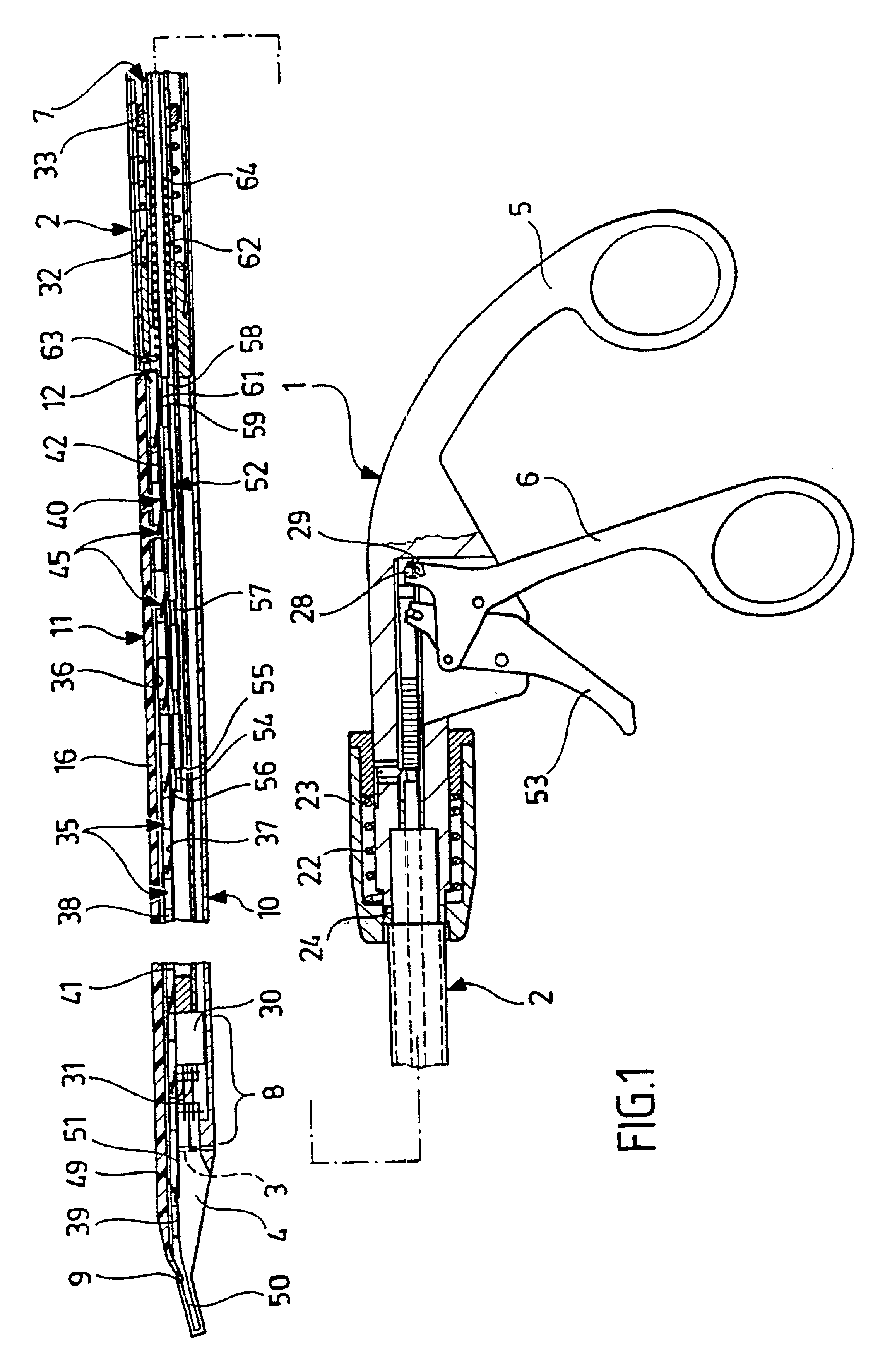
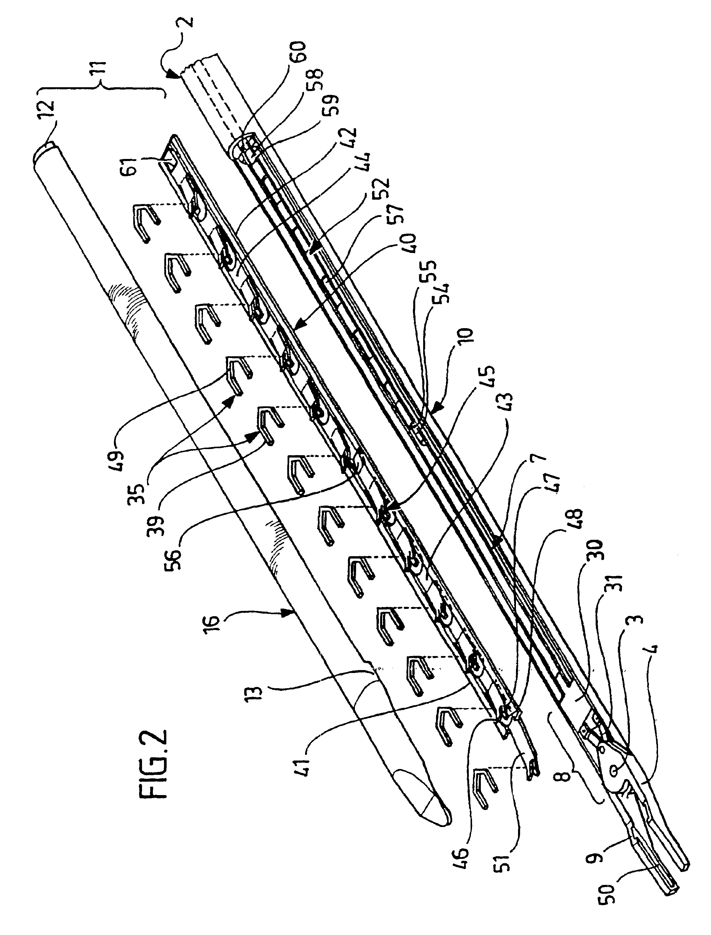
The placing instrument shown in the drawings comprises a handle 1 and a shaft pipe 2 attached to said handle in a way that it is pivotable around its longitudinal axis and detachable. The outside diameter of said shaft pipe is small in comparison with its length. For example the shaft pipe can be 25 cm long, the outside diameter 10 mm or less. At the free end of the shaft pipe 2 two jaws 4 of a plier-like placing tool are arranged that are pivotable around their common swivelling axis 3 and that can be opened and closed from the handle 1 through a locking mechanism arranged in the interior of the shaft pipe. For this purpose the handle 1 is rigidly connected to the first ring handle 5 opposite which a second ring handle 6 is pivotably attached to the handle 1. This second ring handle is pivotably connected to a push-and-pull bar in the form of a sleeve 7 that runs through the whole shaft pipe 2 up to the locking mechanism 8. By pivoting the ring handles 5 and 6 towards each other th...


PUM


Abstract

An instrument for placing U-shaped surgical clips comprising a magazine that has a distal and a proximal end in which several clips are arranged one behind the other in a guide that can be pushed in longitudinal direction. On the lower side of the magazine, a feeding plate which by means of flexible lugs is in contact with the back sides of the clips and can be pushed forwards and backwards by means of a pushing device over at least a distance between one clip and the next clip parallel to the guide of the magazine is provided. The movement of pushing forward shifts all the clips in the direction of the distal end of the magazine. When the feeding plate is pushed forwards, the pushing device contacts said feeding plate at a point which is at a distance of at least half a length of the feeding plate away from the proximal end of the feeding plate.

Description

The present disclosure relates to the subject matter disclosed in the international application No. PCT / EP00 / 07010 of Jul. 21, 2000, which is incorporated herein by reference in its entirety and for all purposes.BACKGROUND OF THE INVENTIONThe invention relates to an instrument for placing U-shaped surgical clips comprising a magazine that has a distal end and a proximal end and in which several clips are arranged one behind the other in a guide and can be moved in the longitudinal direction. On the lower side of the magazine, a feeding plate is provided which contacts the back side of the clips by means of flexible lugs and which can be pushed forwards and backwards parallel to the guide of the magazine over at least the distance between two clips by means of a pushing device. The pushing device creates a pushing movement which shifts all the clips in the direction of the distal end of the magazine.A placing instrument of this kind is for example known from DE 196 03 889 A1. In the ...

Claims


Application Information

Patent Timeline
IPC IPC(8): A61B17/12A61B17/128
CPCA61B17/1285
Inventor MAYENBERGER, RUPERT
Owner AESCULAP AG
Why Eureka
Try Eureka