Electrical power management system providing momentarily high power to a load

a power management system and load technology, applied in emergency power supply arrangements, relays, transportation and packaging, etc., can solve the problems of large capacitance of capacitors, low energy utilization efficiency, and small portion of capacitor energy stored in them

Inactive Publication Date: 2000-11-28
TELEFON AB LM ERICSSON (PUBL)
View PDF11 Cites 52 Cited by
  • Summary
  • Abstract
  • Description
  • Claims
  • Application Information

AI Technical Summary

Problems solved by technology

The drawback of these known constructions is that only a very small portion of the energy stored in the capacitor can be used to assist the power supply in supplying power to a load which momentarily requires high power.
Due to this low efficiency of energy usage a large capacitance must be used to provid

Method used


Image

  • Electrical power management system providing momentarily high power to a load
  • Electrical power management system providing momentarily high power to a load
  • Electrical power management system providing momentarily high power to a load

Examples


Embodiment Construction

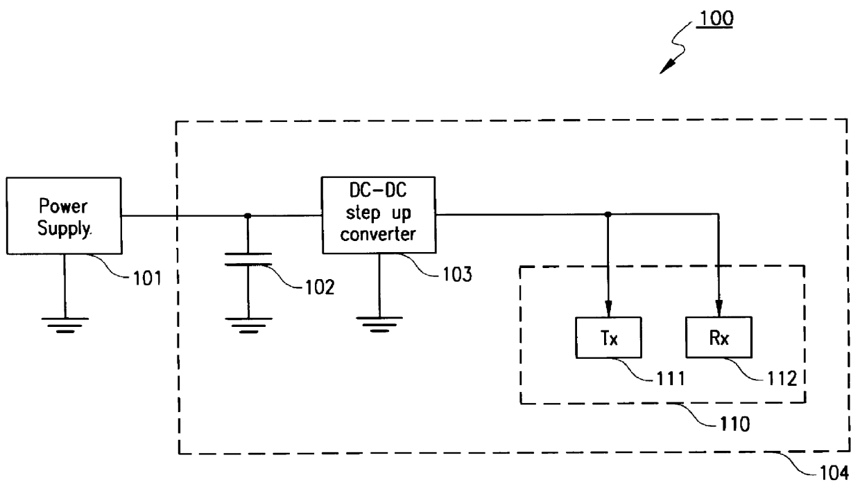
FIG. 1 shows a block diagram of a prior art electrical power management system 100. A power supply 101 is connected to a first terminal of a capacitor 102 and to an input terminal of a DC-DC step up converter 103. The second terminal of the capacitor 102 is connected to ground potential. The output terminal of the DC-DC step up converter 103 is connected to a load 110. In this example, the load 110 comprises a radio transmitter 111 and a radio receiver 112.

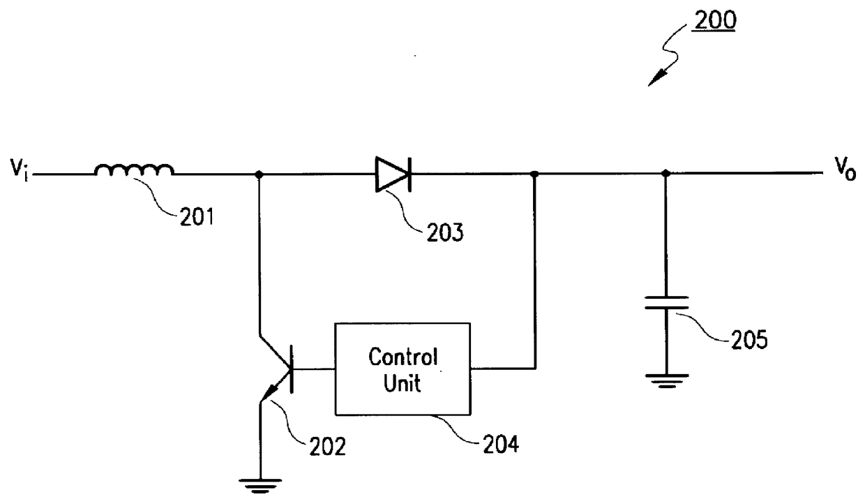
FIG. 2 shows a block diagram of a DC-DC step up converter 200. An input terminal for receiving an input voltage, v.sub.i, is connected to a first terminal of an inductor 201. The second terminal of the inductor 201 is connected to the collector of a bipolar transistor 202 and to the anode of a diode 203. The cathode of the diode 203 is connected to an output terminal for delivering an output voltage, v.sub.o, and to an input of a control unit 204 and to a first terminal of a capacitor 205. An output of the control unit is connecte...


PUM


Abstract

An electrical power management system (300) is disclosed comprising a power supply (301) which, when a first switch (302) and a third switch (306) are closed, provides power to a DC-DC step up converter (303) which, in turn, supplies power to a load (310) and simultaneously stores energy in a capacitor (305). In the case where the load momentarily requires more power than can be provided by the power supply, the first switch (302) and the third switch (306) are opened and a second switch (304) is closed. Energy previously stored in the capacitor (305) is now provided to the DC-DC step up converter (303) thereby allowing an efficient use of energy stored in the capacitor.

Description

TECHNICAL FIELD OF INVENTIONThe invention relates to an electrical power management system and, in particular, to an electrical power management system providing momentarily high power. This kind of power management systems are found in, for example, radio devices requiring momentarily high power during transmission.DESCRIPTION OF RELATED ARTA first known form of an electrical power management system comprises a power supply providing a voltage to a DC-DC step up converter. The voltage at the output of the DC-DC step up converter provides power to a radio transmitter. To handle momentarily high power demands from the transmitter the output voltage of the power supply provides energy to a capacitor. When the transmitter momentarily uses more energy than can be supplied by the power supply alone, energy stored in the capacitor will be provided to the DC-DC converter in addition to the power supplied by the power supply.A second known form of an electrical power management system is di...

Claims


Application Information

Patent Timeline
IPC IPC(8): H02J7/00H02J7/34
CPCH02J7/345H02J7/0065H02J2207/20
Inventor SODERHALL, ANDERS
Owner TELEFON AB LM ERICSSON (PUBL)
Why Eureka
Try Eureka