Intervertebral disk prosthesis

a technology for intervertebral disks and prostheses, which is applied in the field of intervertebral disk prosthesis, can solve the problems of reducing the thickness of the disk, severe pain sensation, and limiting the patient's ability to move, and achieves a large amount of relative mobility

Active Publication Date: 2005-02-10
ABBOTT SPINE INC
View PDF62 Cites 212 Cited by
  • Summary
  • Abstract
  • Description
  • Claims
  • Application Information

AI Technical Summary

Benefits of technology

[0006] A first object of the present invention is to provide an intervertebral disk prosthesis suitable for being put into place by the posterior technique and which nevertheless provides a large amount of relative mobility for the vertebrae between which the prosthesis is located.

Problems solved by technology

This degeneration leads to a reduction in the thickness of the disk and can lead to very severe sensations of pain.
That technique naturally presents the drawback, particularly if applied to several vertebrae, of considerably limiting the patient's ability to move.
Another problem which arises with intervertebral disk prostheses is the surgical technique for putting such a prosthesis into place.
It will also be understood that when using the posterior technique, one of the major difficulties lies in the fact that the spinal cord is disposed between the outer posterior face of the vertebral column and the intervertebral plates between which the intervertebral disk prosthesis is to be placed.
However, the prosthesis described in that document gives only very limited mobility (flexion-extension) between the vertebrae between which the prosthesis is installed.

Method used


Image

  • Intervertebral disk prosthesis
  • Intervertebral disk prosthesis
  • Intervertebral disk prosthesis

Examples


first embodiment

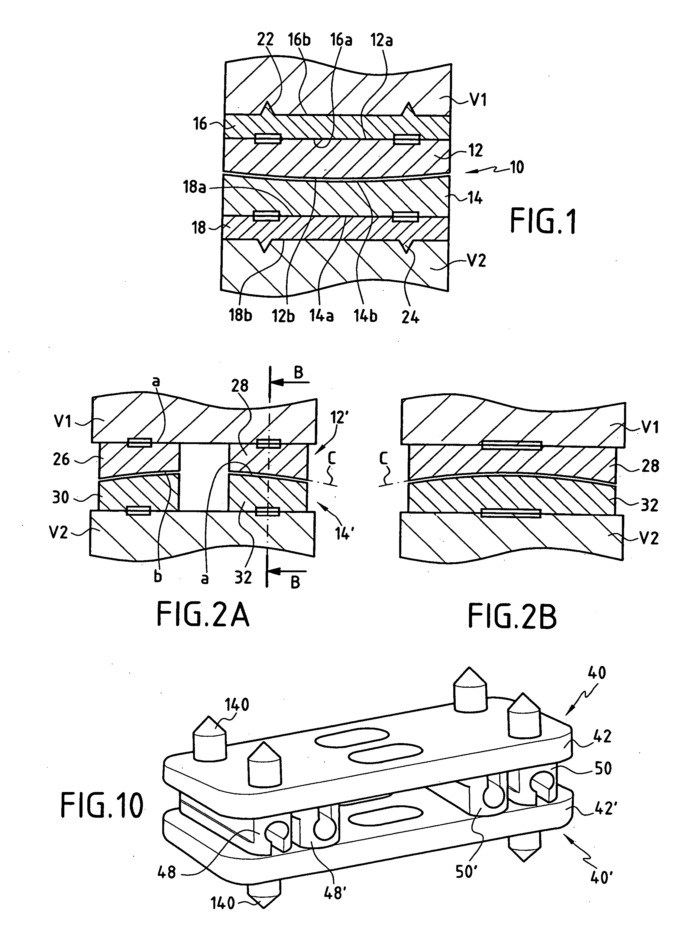
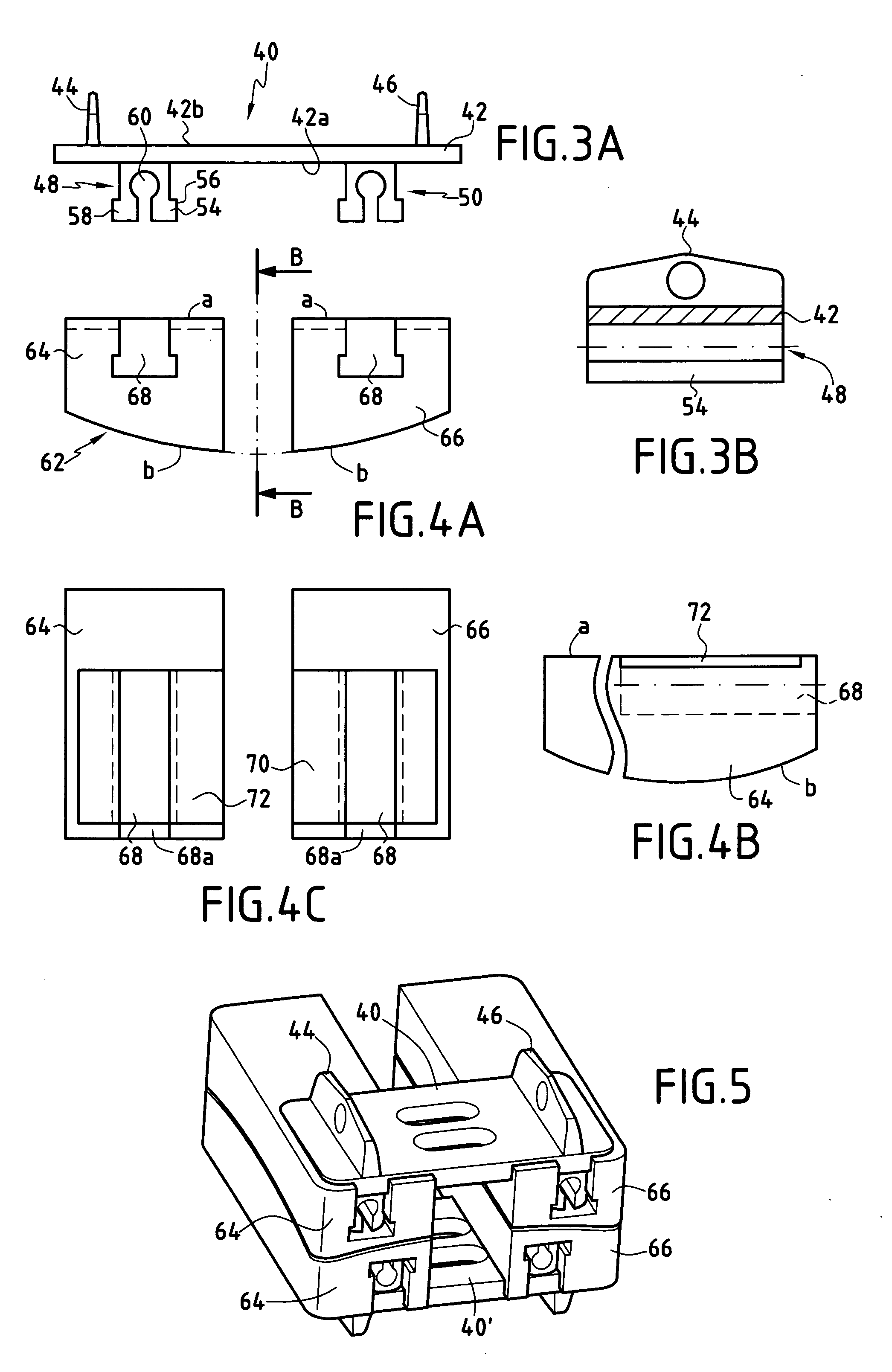
[0077] With reference to FIGS. 3, 4, and 5, the intervertebral disk prosthesis is described.

[0078] In FIGS. 3A and 3B, there can be seen a fixing element referenced 40. The fixing element 40 is constituted by a plate 42 having an anchoring face 42b provided with two transverse ribs 44 and 46 which constitute parts for anchoring in a vertebra. The co-operation face 42a of the plate 42 is fitted with two locking members for locking to the prosthesis element. Each of the locking members 48 and 50 is constituted by a strip 54 extending parallel to the ribs 44. The right section of each strip 54 is generally T-shaped, the strip comprising two flanges 56 and 58 in its portion that is furthest from the plate 42. In addition, in order to enable the strips to deform elastically to a certain extent, each of them has a longitudinal slot 60.

[0079] In FIGS. 4A, 4B, and 4C, there can be seen a prosthesis element 62 which is constituted by two separate parts 64 and 66. The active faces b of the p...

second embodiment

[0089]FIGS. 7A, 7B, and 7C show the prosthesis elements of the prosthesis constituting the The prosthesis element 100 is constituted by a massive part whose co-operation face a presents a shoulder 102 defining a setback portion 104 with the length of the setback portion 104 corresponding to the width of the plate 82 of the fixing element 80. A locking member 106 projects from the setback portion 104. The shoulder 102 corresponds to the thickness of the plate 82. This locking member which is preferably circularly symmetrical about the axis xx′ is constituted by a head 108 and a body 110. The diametral section of the locking member 108 is of a shape which corresponds to the shape of the T-groove 88 formed in the plate 82 of the fixing element 80. The active or contact face b of the prosthesis element 100 comprises a substantially plane portion 112 and a portion 114 in the form of a concave spherical cap.

[0090] The second prosthesis element 120 is identical to the prosthesis element 1...


PUM


Abstract

The invention provides an intervertebral disk prosthesis. The prosthesis comprises: a first fixing element having both an anchoring first face for anchoring in one of the vertebrae and a co-operation second face; a second fixing element having both an anchoring first face for anchoring in the other vertebrae and a co-operation second face; a first prosthesis element having both an active first face and a co-operation second face, said co-operation faces of the first fixing element and of the first prosthesis element serving to fasten the two elements together; a second prosthesis element having both an active first face and a co-operation second face, said co-operation faces of the second fixing element and of the second prosthesis element serving to fasten the two elements together; and each of said active faces of the prosthesis elements defining at least a portion of a spherical cap that is respectively concave or convex.

Description

[0001] The present invention relates to an intervertebral disk prosthesis and to a method of implanting said prosthesis. BACKGROUND OF THE INVENTION [0002] One of the pathological conditions of the vertebral column consists in degeneration of the disks that are interposed between the vertebrae of the vertebral column. This degeneration leads to a reduction in the thickness of the disk and can lead to very severe sensations of pain. When degeneration reaches an advanced stage, it is necessary to remove the natural intervertebral disk and to replace it. In the most frequent cases, a system of intervertebral spacers or cages is put into place to maintain given spacing between the vertebrae and to prevent the two vertebrae from moving relative to each other. That technique naturally presents the drawback, particularly if applied to several vertebrae, of considerably limiting the patient's ability to move. [0003] Another possible technique consists in replacing the natural intervertebral...

Claims


Application Information

Patent Timeline
Patent Type & Authority Applications(United States)
IPC IPC(8): A61F2/00A61F2/30A61F2/44
CPCA61F2/4425A61F2002/30383A61F2002/30387A61F2002/3039A61F2002/30604A61F2220/0025A61F2002/30841A61F2002/30884A61F2002/30892A61F2002/443A61F2002/448A61F2002/30649
Inventor BELLIARD, KARLLE COUEDIC, REGIS
Owner ABBOTT SPINE INC
Why Eureka
Try Eureka