Drain cover assembly

Inactive Publication Date: 2005-02-01
SAINT ISLAND INT
View PDF1 Cites 19 Cited by
  • Summary
  • Abstract
  • Description
  • Claims
  • Application Information

AI Technical Summary

Benefits of technology

Therefore, the object of the present invention is to provide a drain cover assembly that can overcome the aforesaid drawbacks associated with the prior art.
According to the present invention, a drain cover assembly comprises a drain cover unit and a closure device. The drain cover unit includes a cover plate formed with a drain hole. The closure device is operable so as to close and open the drain hole, and includes a pivot arm having amounting portion connected pivotally to the cover plate, a flow control portion extending from and disposed on a first side of the mounting portion and registered w

Problems solved by technology

1. Closing and opening of the drain holes 12 is possible due to the resilient characteristics of the bottom plate 14. However, since the bottom plate 14 is likely to suffer from elastic fatigue after a period of use, the bottom plate 14 will eventually be unable to close the drain holes 12.
2. Since there is always a clea

Method used


Image

  • Drain cover assembly
  • Drain cover assembly
  • Drain cover assembly

Examples


Example

Before the present invention is described in greater detail with reference to the accompanying preferred embodiments, it should be noted herein that like elements are denoted by the same reference numerals throughout the disclosure.

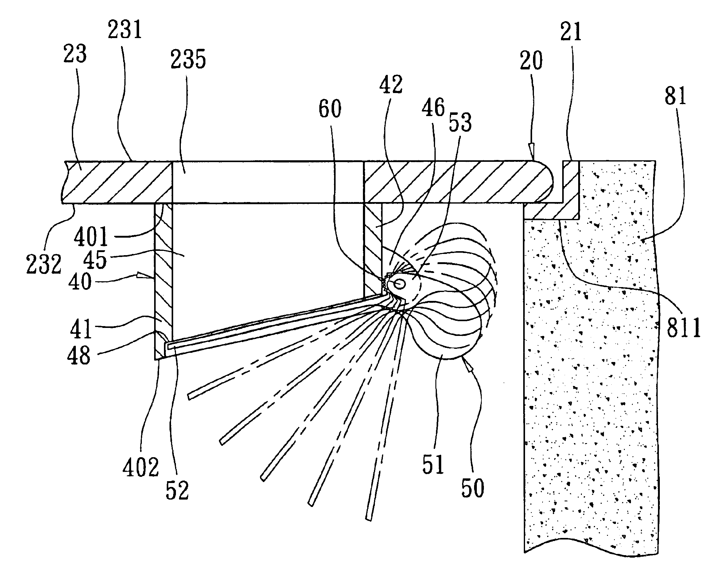
Referring to FIGS. 4 and 6, the first preferred embodiment of a drain cover assembly according to the present invention is shown to be mounted between two drainage walls 81 of a drainage structure 82. Each of the drainage walls 81 has a recessed top edge 811.

The drain cover assembly includes a drain cover unit 20 seated on the recessed top edges 811 of the drainage walls 81, and a closure device 30.

The drain cover unit 20 includes a cover plate 23, a hollow seat frame 21 for receiving the cover plate 23 therein, and a pivot pin unit 22 for retaining pivotally the cover plate 23 in the seat frame 21.

In this embodiment, the seat frame 21 includes opposite first and second angled plates 211, 212, and opposite third and fourth angled plates 213, 214 that inte...


PUM


Abstract

A drain cover assembly includes a closure device operable so as to close and open a drain hole in a cover plate of a drain cover unit. The closure device includes a pivot arm having a mounting portion connected pivotally to the cover plate, a flow control portion extending from and disposed on a first side of the mounting portion and registered with the drain hole, and a weighted portion extending from and disposed on a second side of the mounting portion and having a weight sufficient to overcome the weight of the flow control portion so as to cause the pivot arm to pivot from an open position to a normal closed position. The pivot arm pivots to the open position when the flow control portion is subjected to an applied load through the drain hole that is sufficient to overcome the weight of the weighted portion.

Description

BACKGROUND OF THE INVENTION1. Field of the InventionThe present invention relates to a drain cover assembly, more particularly to a drain cover assembly that includes a closure device for closing a drain hole in a cover plate of a drain cover unit.2. Description of the Related ArtReferring to FIGS. 1 to 3, a conventional drain cover assembly 10 is shown to include a drain cover plate 11 that is formed with a plurality of drain holes 12, and a bottom plate 14 that is fastened to a bottom side of the cover plate 11 with the use of a fastener 13 so as to close the drain holes 12. In a normal state, by virtue of inherent resiliency of the bottom plate 14, the drain holes 12 are closed. However, when water, such as rainwater, fills the drain holes 12, the water applies a load on the bottom plate 14, which causes the latter to flex, thereby opening the drain holes 12 for draining purposes.The following are some of the drawbacks of the aforesaid conventional drain cover assembly 10:1. Clos...

Claims


Application Information

Patent Timeline
IPC IPC(8): E03F5/04F16K17/02F16K17/12F16K1/20F16K1/18
CPCE03F5/0405F16K1/2021F16K17/12F16K1/2028E03F2005/0414E03F2005/0416E03F2005/0417Y10T137/6988Y10T137/7903
Inventor HSIEN, TUNG-MIN
Owner SAINT ISLAND INT
Why Eureka
Try Eureka