

Carbon-based weld blanket
a technology of weld blankets and carbon fibers, which is applied in the field of weld blankets, can solve the problems of molten weld spatter damage, heavy and cumbersome weld blankets, and ineffective stopping of spatter burns, and achieves the effects of reducing the risk of burns, and reducing the service life of weld blankets
- Summary
- Abstract
- Description
- Claims
- Application Information
AI Technical Summary
Benefits of technology
Problems solved by technology
Method used
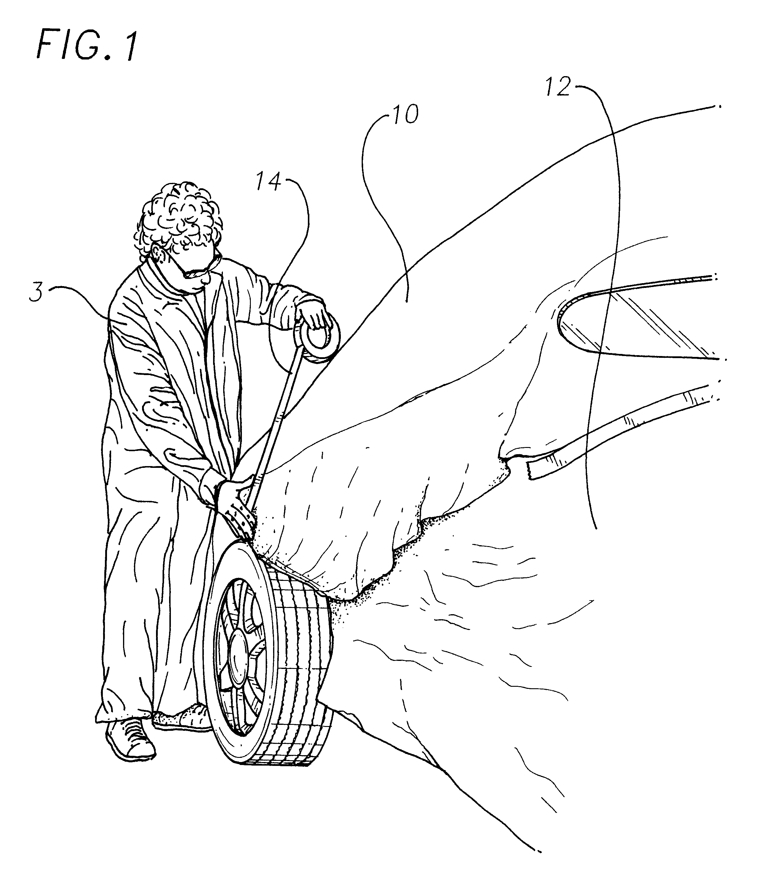
Image

Examples
Embodiment Construction
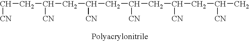
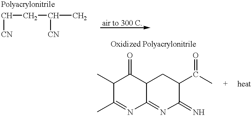
Staple length fibers, generally know as pre-oxidized PAN fibers, are made into batts by use of a textile card. Textile cards convert staple fibers into webbing, primarily held together via light entanglement and fiber to fiber cohesion. The fibers in the webbing are primarily orientated in a single direction; orientation and density are increased via crosslapping. The crosslapped webbing is generally referred to, in the industry, as batting.
The invention makes use of the needle punching technology to mechanically lock the staple fibers together, thus forming a stable, polyacrylonitrile fabric structure. Needle punching technology makes use of a set of barbed needles, which is mechanically moved up and down through a batt of carded staple fiber. As the needle moves through the batt, the barbs, located along the needle's length, capture individual staple fibers. Through mechanical needling action the fibers are intermingled with each other and simultaneously compacted. This process re...
PUM
| Property | Measurement | Unit |
|---|---|---|
| thickness | aaaaa | aaaaa |
| flexibility | aaaaa | aaaaa |
| weight | aaaaa | aaaaa |
Abstract
Description
Claims
Application Information