Liquid analysis cartridge

a liquid analysis and cartridge technology, applied in the field of microfluidic cartridges, can solve the problems of inability to accurately analyze the sample, impracticality of quantitative analysis, and inability to use more than one analysis method sequentially, etc., to facilitate sample reconstitution and rapid and effective reconstitution

Inactive Publication Date: 2005-02-08
UNIV OF WASHINGTON
View PDF127 Cites 185 Cited by
  • Summary
  • Abstract
  • Description
  • Claims
  • Application Information

AI Technical Summary

Benefits of technology

The present invention provides an apparatus and method for storing a particle-containing liquid. The storage apparatus comprises a fluidic convoluted flow channel having a plurality of particle capture regions therein. Particle capture regions are bends in the channel that provide local gravitational minima. When sample flow is arrested (i.e. stopped or slowed) during operation or storage, each of the particles sediments in the nearest particle capture region. Unlike a storage reservoir, the particles do not aggregate in a single clump. Because the particles are locally captured in a plurality of regions, it is possible to rapidly and effectively reconstitute the sample following sedimentation. The storage channel is preferably spatially periodic, where the term spatially periodic channel is used herein for a channel having a substantially constant number of particle capture regions per unit volume. Spatial periodicity facilitates sample reconstitution. The storage channel is more preferably an isotropic spatially periodic channel, where the term isotropic is used herein for a channel suitable for storing a particle-containing liquid regardless of channel orientation.
This invention further provides a fluidic analysis cartridge having a convoluted storage channel therein. The cartridge contains a sample inlet, a convoluted sample storage channel in fluidic connection with the inlet, an analysis channel, having an analysis region, in fluidic connection with the storage channel, and a valve interface positioned between the storage channel and the analysis region. The inlet includes an inlet shut-off interface to prevent leakage of the stored sample through the inlet. The cartridge further includes a resuspension pump interface to resuspend a sedimented sample by sweeping the sample from the storage channel in a continuous or reversing flow. The convoluted storage channel enables accurate analysis of particle-containing samples. The sample analysis region provides for detection by any means known in the art, for example optical, electrical, pressure sensitive, or flow sensitive detection. For electrical detection, the cartridge can include an electrical interconnect. For optical detection, the cartridge can include a window positioned over the analysis region. The optical analysis can employ optical absorption, fluorescence, luminescence or scattering. Particularly useful are absorption and flow cytometric analyses.

Problems solved by technology

A practical limitation for particle-containing liquids such as blood is the sedimentation of particles within the device.
Without a sample management method and apparatus for sedimentation mitigation, quantitative analysis, especially using more than one analysis method sequentially, is impractical.
Moreover, if samples are first collected and then transported to a measurement apparatus, as in a clinical setting or in field sampling, particle sedimentation can make accurate analysis impossible.
Because of particle sedimentation, these devices are useful only for samples without particles.
However, without sedimentation mitigation the measurements can be performed only immediately following sample collection.

Method used


Image

  • Liquid analysis cartridge
  • Liquid analysis cartridge
  • Liquid analysis cartridge

Examples


Embodiment Construction

This invention is further illustrated by the following preferred embodiments. In the drawings, like numbers refer to like features, and the same number appearing in more than one drawing refers to the same feature. The members of the flow systems of this invention are fluidically connected. The term “between” refers to the fluidic positioning, which does not necessarily correspond to the geometric positioning. The terms “top”, “bottom” and “side” refer to the orientation in the drawings, which is not necessarily the orientation of the members in operation.

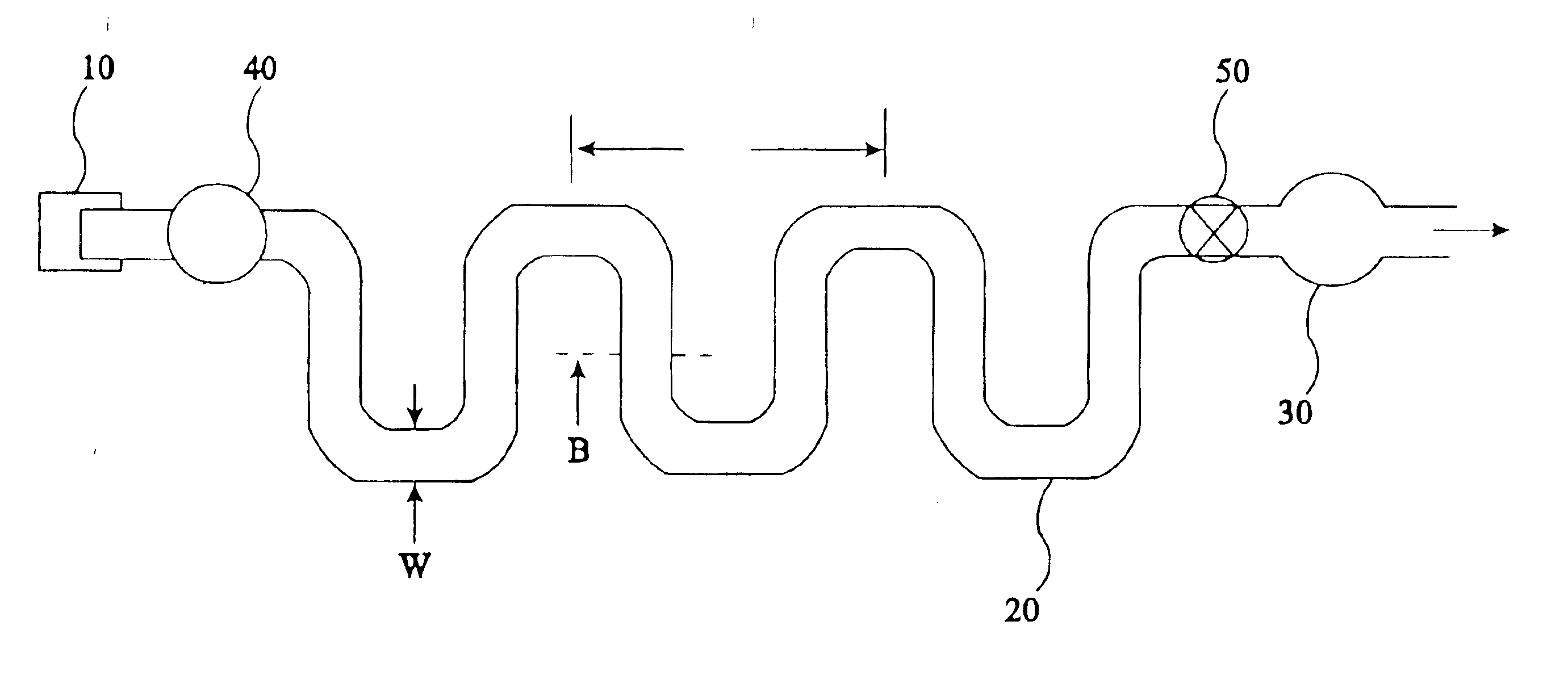
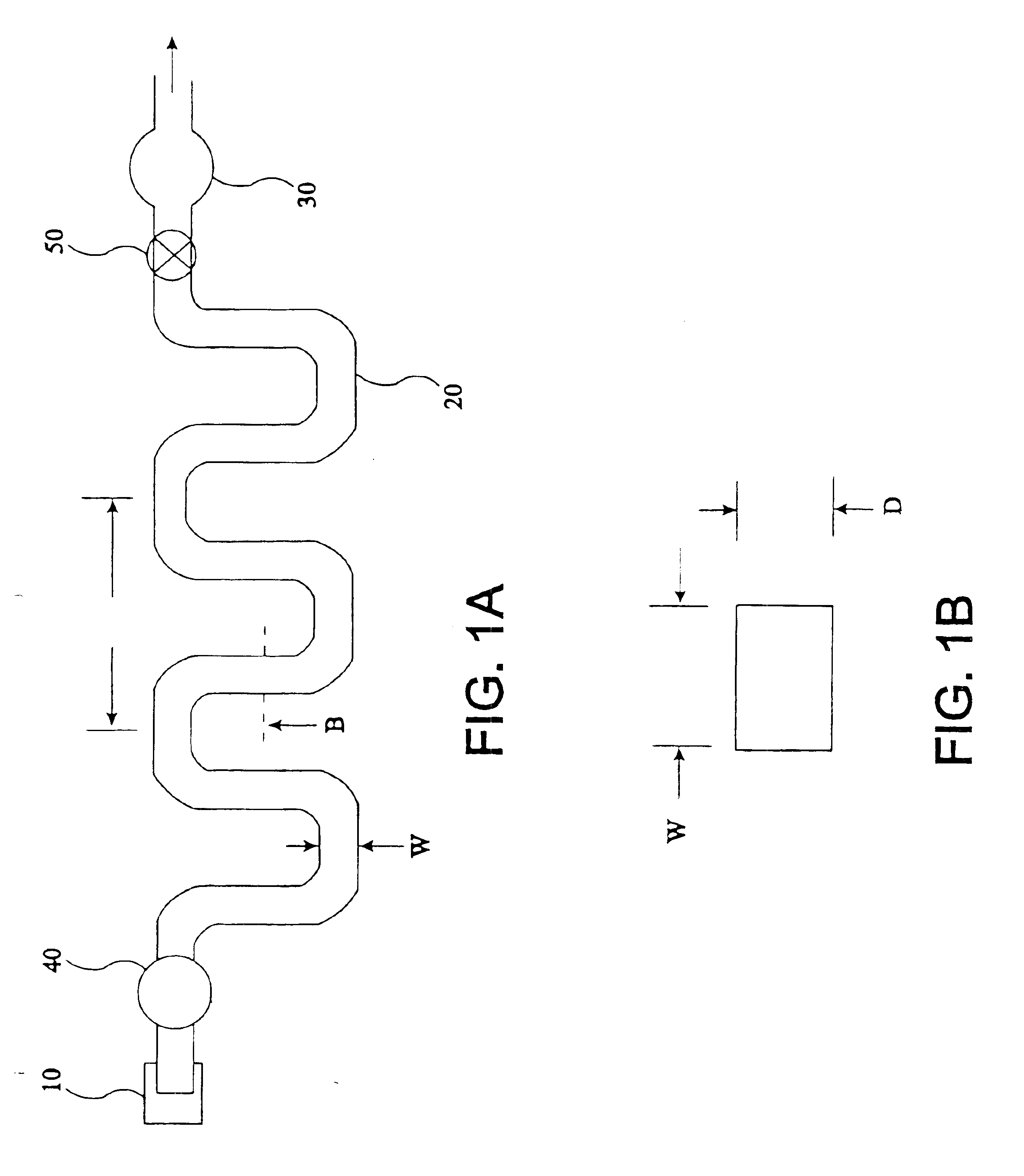
FIG. 1 shows the flow system contained within the cartridge of this invention. The term cartridge is used herein for a fluidic device which is preferably, but not necessarily, disposable and which can be coupled with measurement, pumping, electronic, fluidic or other apparatus. It includes sample inlet 10, convoluted sample storage channel 20, resuspension pump interface 40, sample analysis region 30 and valve interface 50. The flo...


PUM

PropertyMeasurementUnit
depthaaaaaaaaaa
depthaaaaaaaaaa
critical wall shear stressaaaaaaaaaa

Abstract

The present invention provides an apparatus and method for storing a particle-containing liquid. The storage apparatus comprises a microfluidic convoluted flow channel having a plurality of article capture regions. The storage channel is preferably an isotropic spatially periodic channel. Sedimented particles can be resuspended following storage. This invention further provides a microfluidic analysis cartridge having a convoluted storage channel therein. The sample analysis can use optical, electrical, pressure sensitive, or flow sensitive detection. A plurality of analysis channels can be included in a single cartridge. The analysis channels can be joined to reagent inlets for diluents, indicators or lysing agents. A mixing channel can be positioned between the reagent inlet and the analysis region to allow mixing and reaction of the reagent. The cartridge can include additional valves and pumps for flow management. The analysis cartridge can be a self-contained disposable cartridge having an integral waste storage container. This invention further provides a sheath flow assembly. The sheath flow assembly includes a sample channel and first and second sheath fluid channels positioned on either side of and converging with the sample channel. The assembly also includes upper and lower sheath fluid chambers positioned above and below and converging with the sample channel. The flow cartridges of this invention can be formed by molding, machining or etching. In a preferred embodiment they are laminated. This invention further provides a method of fabricating a laminated microfluidic flow device. In the method, flow elements are formed in rigid sheets and abutting surfaces of the sheets are bonded together.

Description

FIELD OF THE INVENTIONThis invention relates to microfluidic cartridges for analysis of liquid samples, and in particular to cartridges having a convoluted sample storage channel and to cartridges having a flow cytometric measuring region.BACKGROUND OF THE INVENTIONWith the advent of micro-machining technology, microfluidic devices have proliferated (for example, U.S. Pat. No. 5,637,469 to Wilding et al., U.S. Pat. No. 4,983,038 to Ohki et al., U.S. Pat. No. 4,963,498 to Hillman et al., U.S. Pat. No. 5,250,263 to Manz et al., U.S. Pat. No. 5,376,252 to Ekstrom et al., E.P. Patent Publication 0381501B1, and Petersen, E. (1982) Proc. of the IEEE, vol. 70, No. 5, pp. 420-457). A practical limitation for particle-containing liquids such as blood is the sedimentation of particles within the device. Following loading the liquid in the device, appreciable particle sedimentation can occur within the time required to position the device in a measurement apparatus. For example, if the sample ...

Claims


Application Information

Patent Timeline
Patent Type & Authority Patents(United States)
IPC IPC(8): B01L3/00G01N15/14B01L99/00
CPCB01F5/0646B01F5/0648B01F13/0059B01L3/502707B01L3/502738B01L3/502746B01L3/502776G01N15/14B01F5/0647Y10T436/118339B01L3/502715B01L3/565B01L2200/025B01L2200/027B01L2200/0636B01L2200/0647B01L2200/10B01L2200/12B01L2200/16B01L2300/0627B01L2300/0636B01L2300/0645B01L2300/0816B01L2300/0861B01L2300/0867B01L2300/0874B01L2300/0883B01L2300/0887B01L2400/0487B01L2400/0655Y10T156/1064Y10T436/117497Y10T436/2575Y10T436/25375Y10T436/25Y10T436/11Y10T436/25125B01F25/4332B01F25/4331B01F25/433B01F33/30
Inventor HOLL, MARK R.EDWARDS, FLOYDMORFF, ROBERT J.KLEIN, GERALD L.
Owner UNIV OF WASHINGTON
Why Eureka
Try Eureka