Unlock instant, AI-driven research and patent intelligence for your innovation.

Pressure regulating valve with adjustment features

a technology of pressure regulating valve and adjustment feature, which is applied in the direction of fluid pressure control, magnetic body, instruments, etc., can solve the problems of increasing manufacturing costs, limiting the variability and accuracy of current rpcv's and related valves, and potentially insufficient valve-to-valve variability and accuracy limitations to meet the needs of future engine designs, etc., to reduce the manufacturing variability of electromagnetic actuators.

Inactive Publication Date: 2005-02-15
FAS CONTROLS
View PDF5 Cites 26 Cited by
  • Summary
  • Abstract
  • Description
  • Claims
  • Application Information

AI Technical Summary

Benefits of technology

In another aspect, the above-noted electromagnetic actuator further includes an armature travel adjustment element, wherein the armature travel adjustment element is disposed to enter a distal end of the tube and is configured for movement in an advancing direction toward a proximal end of the tube and a withdrawing direction away from the proximal end of the tube so as to correspondingly increase or decrease an armature travel within the tube.
In yet another aspect, a method for reducing manufacturing variability in an electromagnetic actuator is provided and comprises the step of proving an electromagnetic actuator. The provided electromagnetic actutator comprises a tube having a proximal and a distal end and a coil disposed about the tube, the coil being electrically connectable to a circuit configured to provide a current to the coil to generate a magnetic field and magnetic flux. A movable armature having a proximal and a distal end is borne within the tube, the armature being at least partially circumscribed by the coil, the armature configured for magnetic coupling with the coil, the magnetic coupling urging the armature to move within the tube and the armature being configured to transmit a force imparted thereto by a magnetic flux output by the coil out of the electromagnetic actuator. The provided electromagnetic actuator also includes at least one of (1) an external flux adjustment element configured for movement within a magnetic flux output by the coil so as to increase a magnetic flux field input to the armature upon movement of the flux adjustment element in a first direction and to decrease a magnetic flux field input to the armature upon movement of the flux adjustment element in a second direction and (2) an external armature travel adjustment element disposed to enter a distal end of the tube and configured for movement in an advancing direction toward a proximal end of the tube and a withdrawing direction away from the proximal end of the tube so as to correspondingly increase or decrease an armature travel within the tube. The method also includes the step of attaching the electromagnetic actuator to a test stand configured to generate an output signal corresponding to a force generated by the armature based on a predetermined current input to the electromagnetic actuator coil. The method also includes the step of adjusting at least one of the external flux adjustment element and the external armature travel adjustment element responsive to the output signal to vary a corresponding magnetic flux field input to the armature and a range of travel permitted thereby so as to correspondingly increase or decrease the output signal until the output signal substantially corresponds to a predetermined output signal or falls within a range of predetermined output signals corresponding to the predetermined current input.

Problems solved by technology

However, current RPCV's and related valves are limited in both valve-to-valve variability and accuracy.
In view of the ever increasing sophistication of automobile engine control systems and omnipresent need for improved fuel efficiency, improved power, and decreased emissions, such valve-to-valve variability and accuracy limitations are potentially insufficient to meet the needs of future engine designs.
Further, such variability undesirably increases manufacturing costs.

Method used


Image

  • Pressure regulating valve with adjustment features
  • Pressure regulating valve with adjustment features
  • Pressure regulating valve with adjustment features

Examples


Embodiment Construction

Features for adjusting an electromagnetic actuated device to enhance accuracy and to minimize variability between manufactured electromagnetic actuated devices. One example of an electromagnetic actuated device includes electromagnetically actuated valves. An example of an electromagnetically actuated valve includes an electromagnetically actuated pressure control valve. One such electromagnetically actuated pressure control valve design is discussed below, by way of example, in relation to the features of adjusting an electromagnetic actuated device associated therewith to enhance accuracy and to minimize variability between such valves.

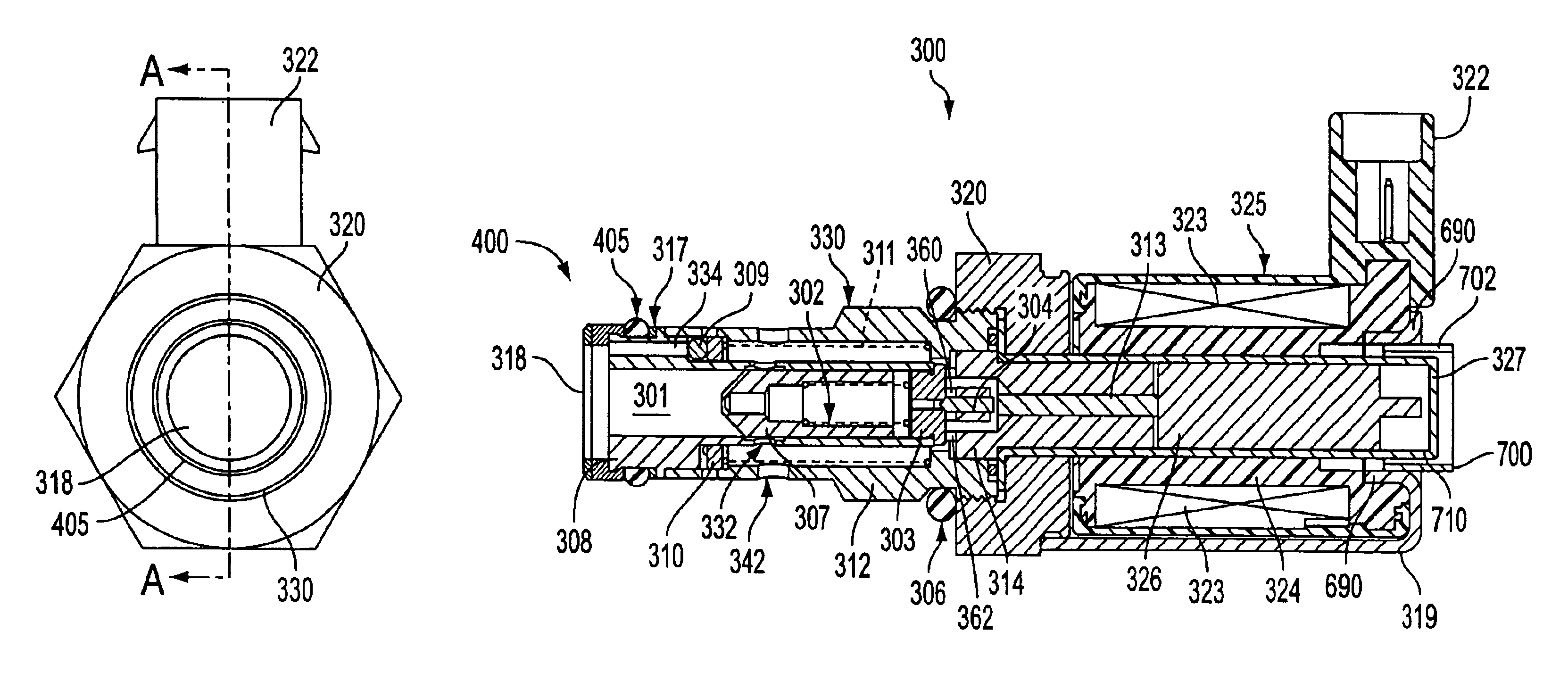
FIG. 4 shows an Injector Pressure Regulator Valve (IPR) 300 in accord with the herein-described embodiment. IPR 300 is an electronically-controlled pilot operated pressure control valve including main poppet 307, pin poppet or secondary poppet 304, push pin 313, and armature 326, each configured for translational or reciprocating motion along a long...


PUM


Abstract

There is provided an electromagnetic actuator which includes a coil disposed about a tube bearing a movable armature, the coil being electrically connectable to a circuit configured to provide a current to the coil to generate a magnetic field and magnetic flux in at least one direction. The movable armature is magnetically coupleable with the coil. A flux adjustment element is also provide and is configured for movement within a magnetic flux output by the coil so as to increase a magnetic flux input to the armature upon movement of the flux adjustment element in a first direction and to decrease a magnetic flux input to the armature upon movement of the flux adjustment element in a second direction, wherein the flux adjustment element is externally disposed about a distal end of the tube.

Description

FIELD OF THE INVENTIONThe invention relates to electomagnetically actuated devices. One example of such device would include electromagnetically actuated valves. One such electromagnetically actuated valve could include, but is not limited to, a pressure control valve, such as, for example, a rail or manifold pressure in Hydraulically-actuated Electronically-controlled Unit Injector (HEUI) fuel systems used in diesel engines.BACKGROUND OF THE INVENTIONGasoline engines use a pressurized fuel system wherein a computer is used to vary the actuation of the fuel injectors to meet a demand based on the input from various sensors. Since gasoline engines have an ignition system to ignite an air / fuel mixture in the cylinders, the fuel pressure only needs to be high enough to provide an adequate spray pattern to ensure efficient combustion. Diesel engines, on the other hand, use heat from compression to ignite the air / fuel mixture. The high compression levels require correspondingly high air / ...

Claims


Application Information

Patent Timeline
IPC IPC(8): F02M57/00F02M57/02F02M59/00F02M59/46G05D16/20
CPCF02M57/025G05D16/2093F02M63/0056F02M59/466G05D16/2097
Inventor PARKER, DAVID G.BABINEAU, JR., ALFRED J.
Owner FAS CONTROLS