Fixture and method for assembling structures

Inactive Publication Date: 2005-03-01
HENDRICKSON USA L L C
View PDF17 Cites 11 Cited by
  • Summary
  • Abstract
  • Description
  • Claims
  • Application Information

AI Technical Summary

Benefits of technology

Objectives of the present invention include providing a fixture and a method for removably and accurately positioning the fixture and a structure to be assembled thereon between a headstock and a tailstock, so that an operator will have 360 degree access to the fixture and the structure.
A further objective of the present invention is to provide such a removable fixture which facilitates efficient loading and unloading of structures onto and from, respectively, the fixture.
Another objective of the present invention is to provide such a fixture that reduces stress on the fixture, and the structure being assembled thereon, during rotation.
These objectives and advantages are obtained by the improved fixture and method for assembling structures of the present invention, the general nature of which may be stated as including, an improved fixture for remo

Problems solved by technology

One disadvantage has been the difficulty of loading and unloading large structures onto the fixture with overhead cranes or lifting tools, and also that the operator/assembler had access to only one side of the fixture.
Heretofore, others have contemplated a removable fixture to overcome the problems of loading/unloading and operator access inherent when the fixture is non-removably mounted on the headstock/tailstock structures, but until applicants' invention the objective has not been satisfactorily achieved.
More particula

Method used


Image

  • Fixture and method for assembling structures
  • Fixture and method for assembling structures
  • Fixture and method for assembling structures

Examples


Example

Similar numerals refer to similar parts throughout the drawings.

DESCRIPTION OF THE PREFERRED EMBODIMENT

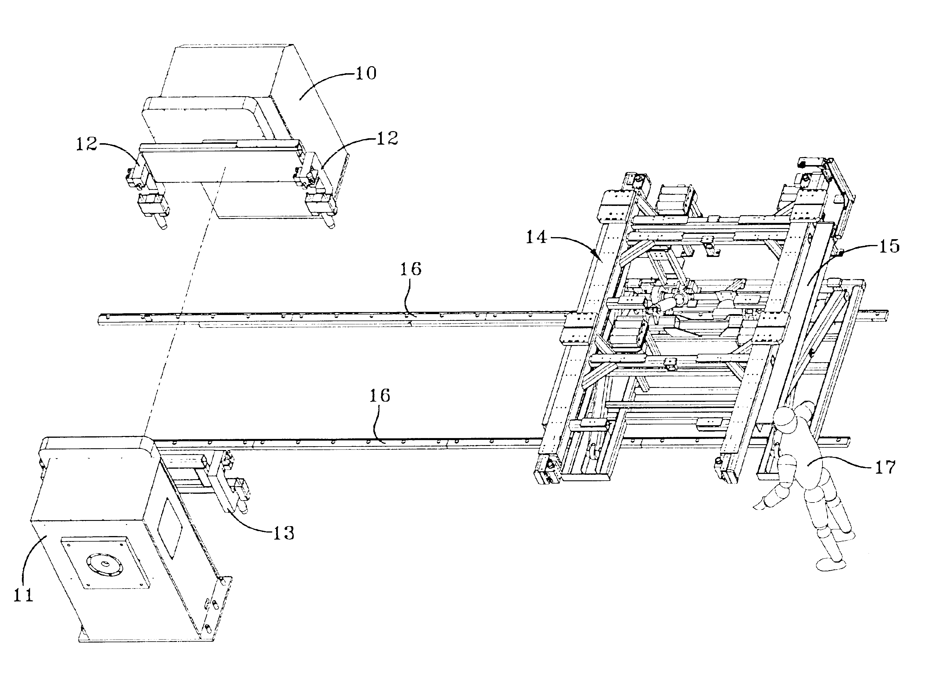
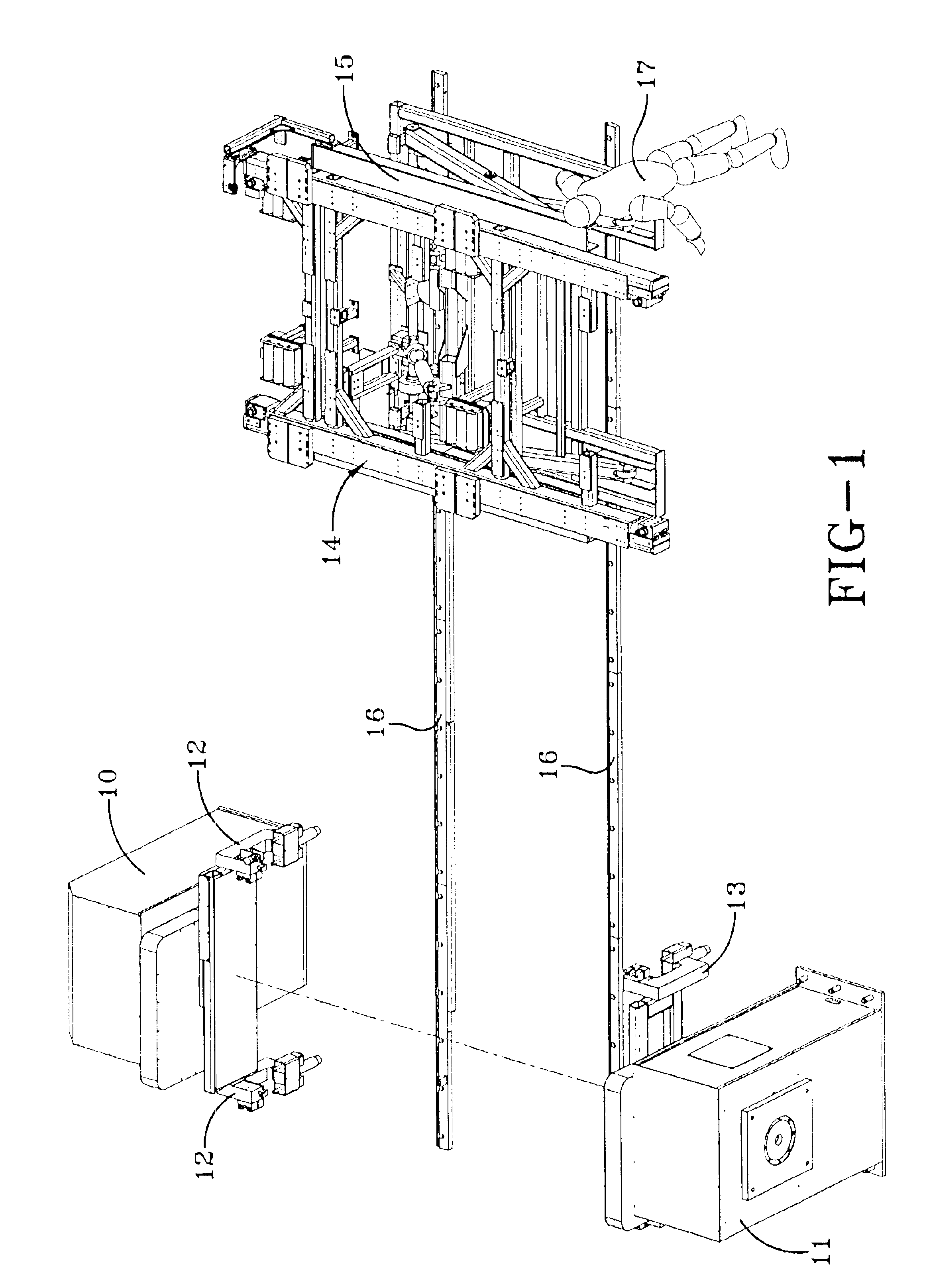
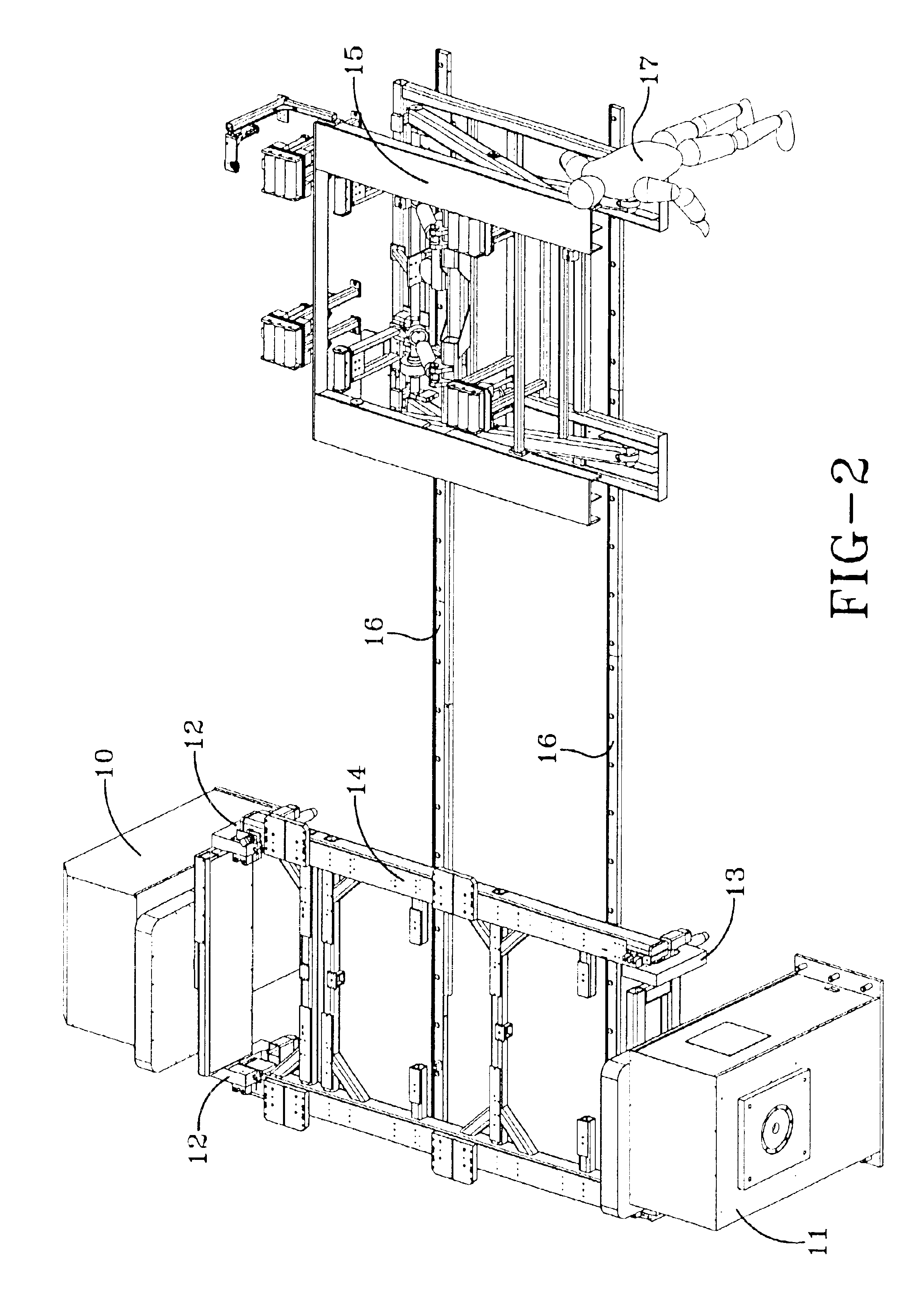
The objectives of the present invention are achieved in the following manner. A conventional stationary driving headstock 10 and a follower tailstock 11 which are spaced-apart and aligned is depicted in the left-hand portion of FIG. 1. Headstock 10 is of a type commonly known in the prior art and includes a pair of headstock arms 12. Similarly, tailstock 11 also is of a type commonly known in the prior art and also includes a pair of tailstock arms 13. Each one of the tailstock arms 13 preferably is generally C-shaped and is adapted for receipt of a locating pin, as will be described in greater detail hereinbelow.

A tool or fixture 14 of the present invention having first and second ends and commonly used in heavy industrial applications for assembling large structures, such as a slider assembly for a semi-trailer, and that can be removably and accurately positioned between headstoc...


PUM

PropertyMeasurementUnit
Stress optical coefficientaaaaaaaaaa
Tensionaaaaaaaaaa

Abstract

An improved fixture and method for assembling a structure, wherein the improved fixture comprises a frame and a pair of position compliance devices. The compliance devices are attached to a selected one of the ends of the fixture frame for engagement with the arms of a selected one of a headstock and a tailstock used to rotate the fixture and structure to be assembled. The compliance devices each comprise a slidable block having a locating pin rotatably mounted therein, which enables the fixture to be accurately and removably positioned between a headstock and a tailstock, serving to reduce unwanted stress on the fixture and the structure to be assembled during rotation. Removability of the fixture and structure to be assembled facilitates convenient loading/unloading of the structure and 360 degree access to the structure and fixture by an operator.

Description

BACKGROUND OF THE INVENTION1. Field of the InventionThe invention relates to an improved fixture and a method for removably and accurately positioning the fixture between a headstock and a tailstock, and in particular to an improved fixture suitable for conveniently loading and unloading large structures to be assembled and that provides an operator with 360 degree access to the improved fixture and the structure. More particularly, the present invention is directed to an improved fixture having a frame and a plurality of position compliance devices, each comprising a movable block having a rotatably mounted locating pin, which enables the fixture to be accurately and repeatably positioned between the headstock and tailstock, and that serves to reduce stress on the fixture and the structure being assembled during rotation, which is undesirable if left unreduced.2. Background ArtFixtures or tools have been used for many years to facilitate the assembly of large structures such as a s...

Claims


Application Information

Patent Timeline
IPC IPC(8): B23Q1/25B23Q1/52B23Q1/00
CPCB23Q1/0063B23Q1/52Y10T29/53961Y10T29/49895Y10T29/49998
Inventor BAUER, ERIC TALBOTTMILLER, PAUL EDWARDWITTLINGER, JEFFREY R.GERSTENSLAGER, GARY E.
Owner HENDRICKSON USA L L C
Why Eureka
Try Eureka