Load pin with increased performance

Active Publication Date: 2012-09-20
HONEYWELL INT INC
View PDF5 Cites 2 Cited by
  • Summary
  • Abstract
  • Description
  • Claims
  • Application Information

AI Technical Summary

Benefits of technology

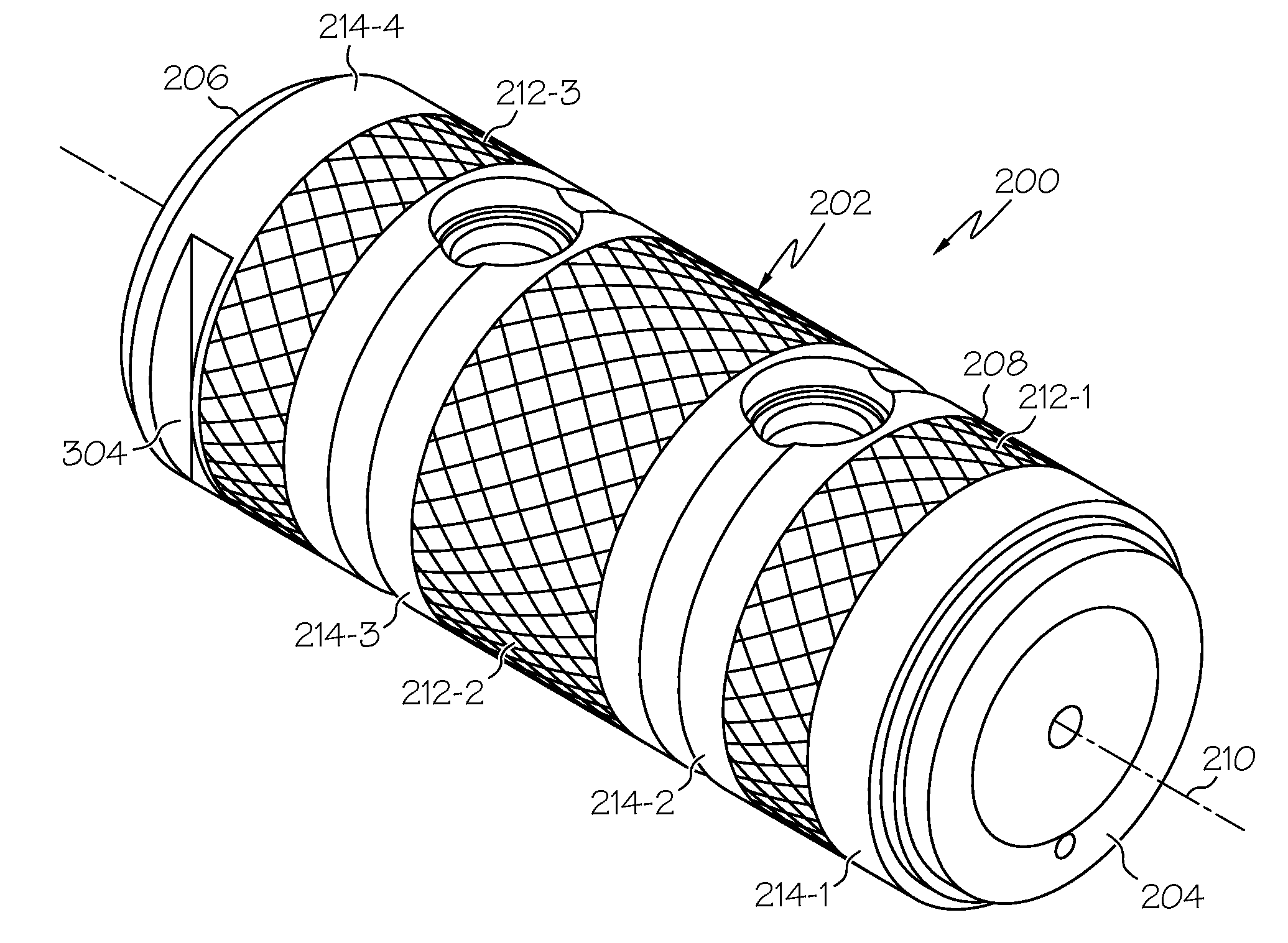
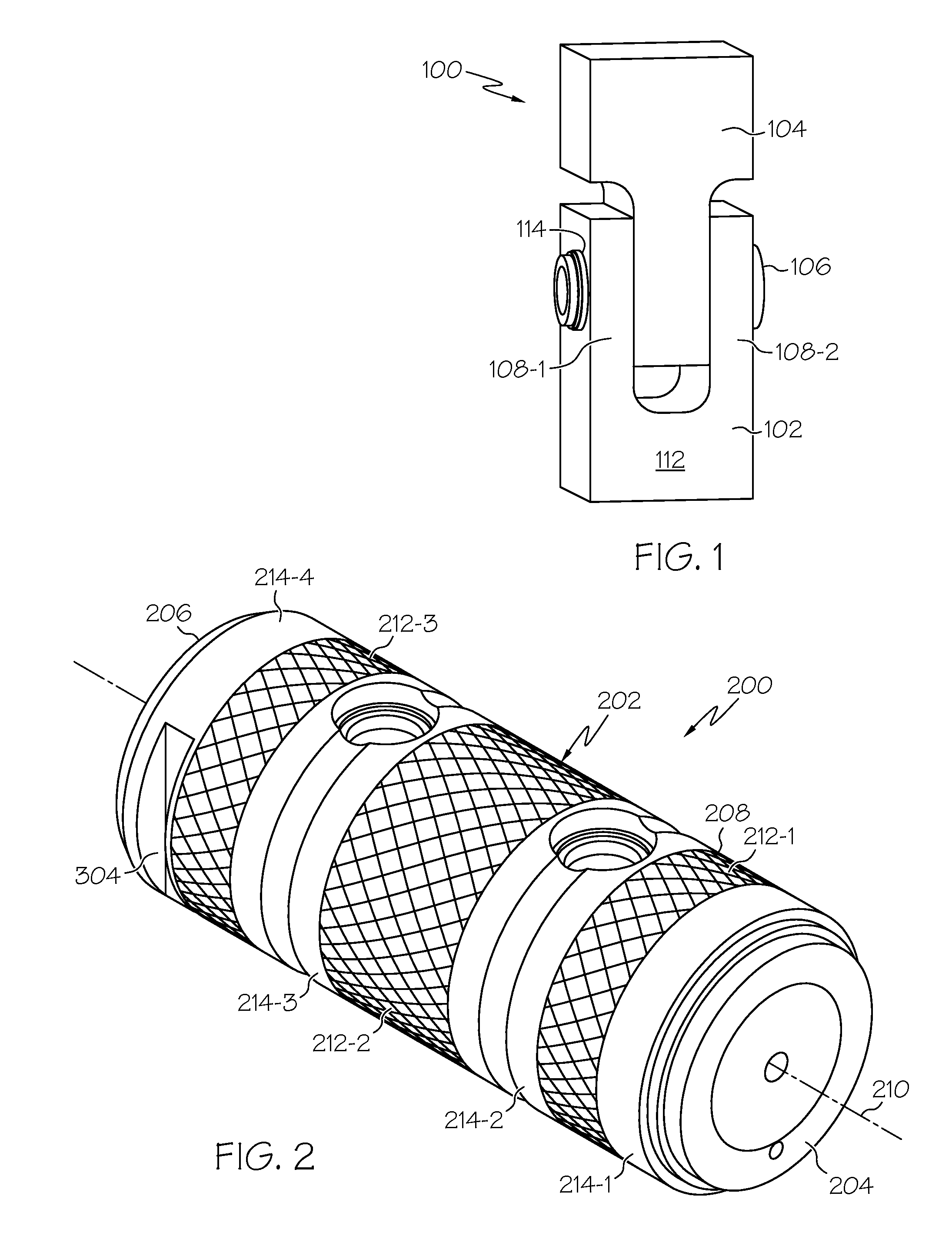
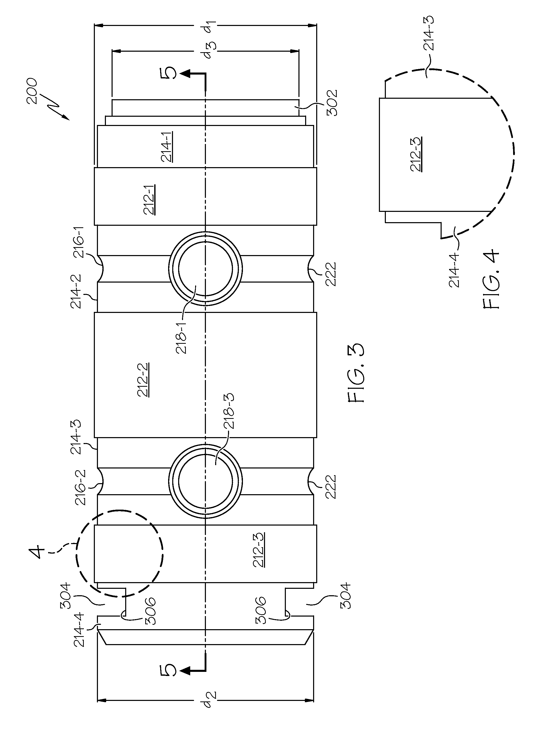
[0025]To facilitate rotation of the load pin 200, one or more adjustment channels 304 may be formed in the outer surface 208 of the main body 202, although the depicted embodiment includes two adjustment channels. The one or more adjustment channels 304 are formed proximate the second end 206 of the main body 202, and are disposed in diametric opposition to each other. Although the one or more adjustment channels 304 may be variously configured, in the depicted embodiment each is configured with a substantially flat bottom surface 306,

Problems solved by technology

Many load pins, such as those described above, may not have sufficiently stiff, isolated ends as compared to the sensing portion, where the strain gages are located.
As a result, it can

Method used


Image

  • Load pin with increased performance
  • Load pin with increased performance
  • Load pin with increased performance

Examples


Example

[0015]The following detailed description is merely exemplary in nature and is not intended to limit the invention or the application and uses of the invention. As used herein, the word “exemplary” means “serving as an example, instance, or illustration.” Thus, any embodiment described herein as “exemplary” is not necessarily to be construed as preferred or advantageous over other embodiments. All of the embodiments described herein are exemplary embodiments provided to enable persons skilled in the art to make or use the invention and not to limit the scope of the invention which is defined by the claims. Furthermore, there is no intention to be bound by any expressed or implied theory presented in the preceding technical field, background, brief summary, or the following detailed description. In this regard, although embodiments of a load pin are described as being implemented in a clevis fastener system, it will be appreciated that the load pin may be implemented in numerous and v...


PUM


Abstract

A load pin includes a main body, a plurality of recesses, and a plurality of sensor pockets. The main body has a plurality of loading surfaces and a plurality of relief surfaces formed therein. Each loading surface is disposed between two of the relief surfaces. The recesses are formed in and extend at least partially around the outer surface of the main body. Each recess has a substantially round inner surface, is formed in a different one of the relief surfaces, and is disposed between a different pair of loading surface. The sensor pockets are formed in the outer surface, extend partially into the main body, are disposed between a pair of loading surfaces, and extend through the recess that is disposed between the same pair of loading surfaces.

Description

TECHNICAL FIELD[0001]The present invention generally relates to load pins, and more particularly relates to a load pin that exhibits improved sensitivity under both tensile and compressive loads.BACKGROUND[0002]Load pins may be used to measure loads in various systems. A load pin equipped with one or more strain gages may be mounted into a machine in place of a shaft, a bolt, a pivot pin, or clevis pin. The strain gages are configured to measure loads in the load pin and to generate a signal proportional to the measured load.[0003]Many load pins, such as those described above, may not have sufficiently stiff, isolated ends as compared to the sensing portion, where the strain gages are located. As a result, it can be difficult to obtain precision loading measurements from the instrumentation. In particular, the load pins may exhibit different behavior under tension and compression. This is typically attributed to the non-uniform loading of the pin under these different loading scenar...

Claims


Application Information

Patent Timeline
IPC IPC(8): G01B5/30F16B19/00
CPCG01L1/2225
Inventor KEMPAINEN, ALAN JOHNJOB, SUNILESWARAN, SIVAPRAKASH
Owner HONEYWELL INT INC
Why Eureka
Try Eureka