
Acoustic guitar resonator
a guitar and resonator technology, applied in the field of stringed musical instruments, can solve the problems of limited control available to guitarists, loud volume, and high cost of outstanding guitar sound, and achieve the effect of achieving quality amplification of guitar sound, amplifying rich guitar sound, and easy inserting of sound characteristics of another material and shap
- Summary
- Abstract
- Description
- Claims
- Application Information
AI Technical Summary
Benefits of technology
Problems solved by technology
Method used
Image

Examples
embodiment 20
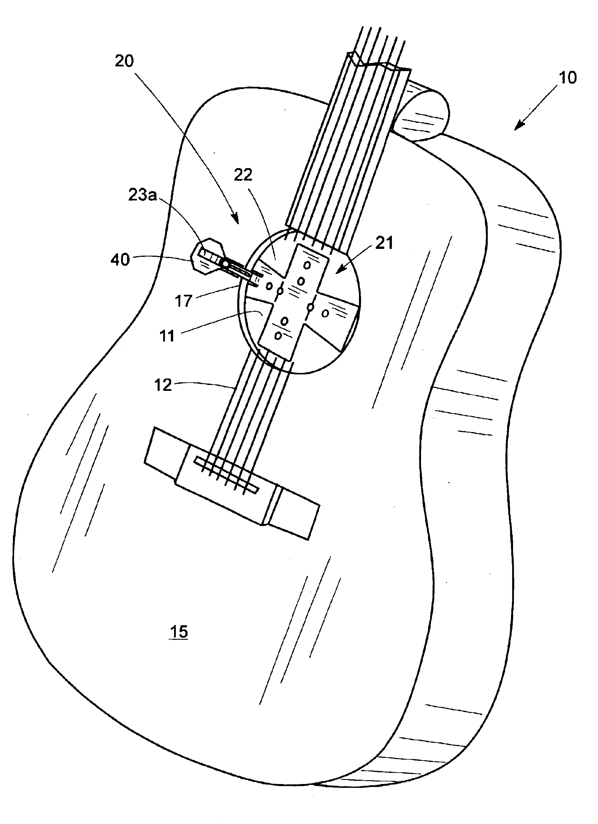
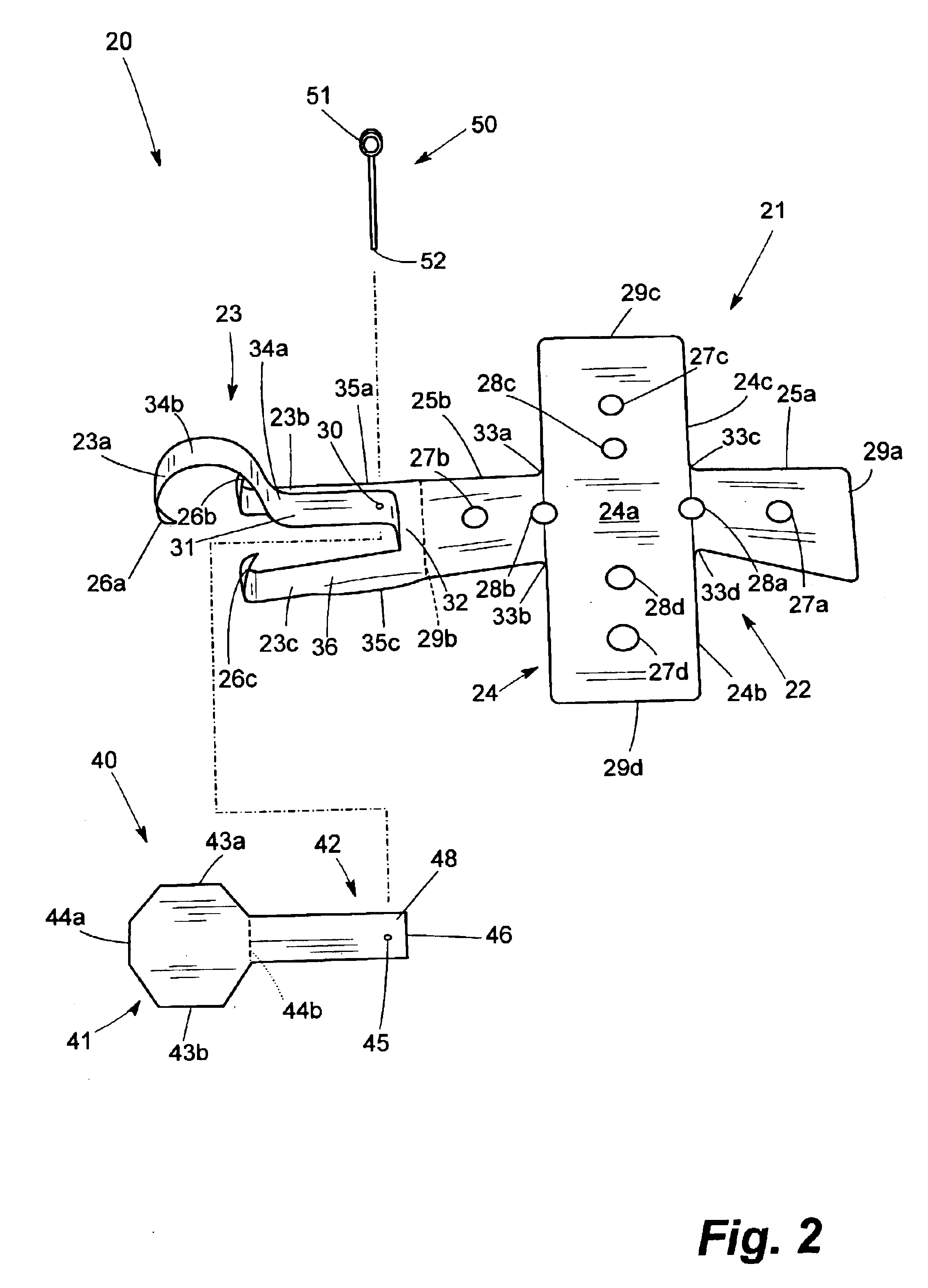
In general, arms 25a and 25b slope gently downward from center section 24a, while arms 24b and 24c bend slightly downward as they extend from center section 24a so to prevent them from rising above the guitar top 15 and injuring the guitarist's fingers when embodiment 20 is placed on guitar 10 and vigorously vibrate. Arms 24b, 24c, 25a and 25b may be adjusted with finger pressure.
In the preferred embodiment, detector-clip 23 extends from arm 25b, also referred to as the clip-arm. (See FIG. 2). Detector-clip 23 comprises base 32 congruous to end 29b (the dotted line) of clip-arm 25b and has prongs that may be used to place resonator 21 cantilevered near the edge defining sound hole 11.
In the preferred embodiment, the width of base 32 at end 29b is about seven-eighth (⅞) of an inch and splits into three prongs at end 36, shown as a dotted line, which is about on-fourth (¼) of an inch away from end 29b. The prongs are referred to as upper prong 23a and under prongs 23b, 23c and are sep...
PUM
 Abstract
Description
Claims
Application Information