Non-optical signal isolator

a non-optical, signal-isolating technology, applied in the field of circuitry, can solve the problems of not operating well at high frequencies, limited isolation levels, and limitations of optical isolators

Inactive Publication Date: 2005-03-29
ANALOG DEVICES INC
View PDF66 Cites 345 Cited by
  • Summary
  • Abstract
  • Description
  • Claims
  • Application Information

AI Technical Summary

Problems solved by technology

Optical isolators present certain limitations, however: among other limitations, they are rather non-linear and not suitable for accurate linear applications, they require significant space on a card or circuit board, they draw a large current, they do not operate well at high frequencies, and they are very inefficient.
They also provide somewhat limited levels of isolation.
However, a conductive shield which provides a significant degree of isolation is not sufficiently transparent for use in this application.
This current potentially can damage the receiving circuit and can trigger a faulty detection.
The patent also mentions, without elaboration, that a transformer with a short R / L time constant can provide an isolation barrier, but such a differential approach is nonetheless undesirable because any mismatch in the non-magnetic (i.e., capacitive) coupling of the windings would cause a common-mode signal to appear as a difference signal.

Method used


Image

  • Non-optical signal isolator
  • Non-optical signal isolator
  • Non-optical signal isolator

Examples


Embodiment Construction

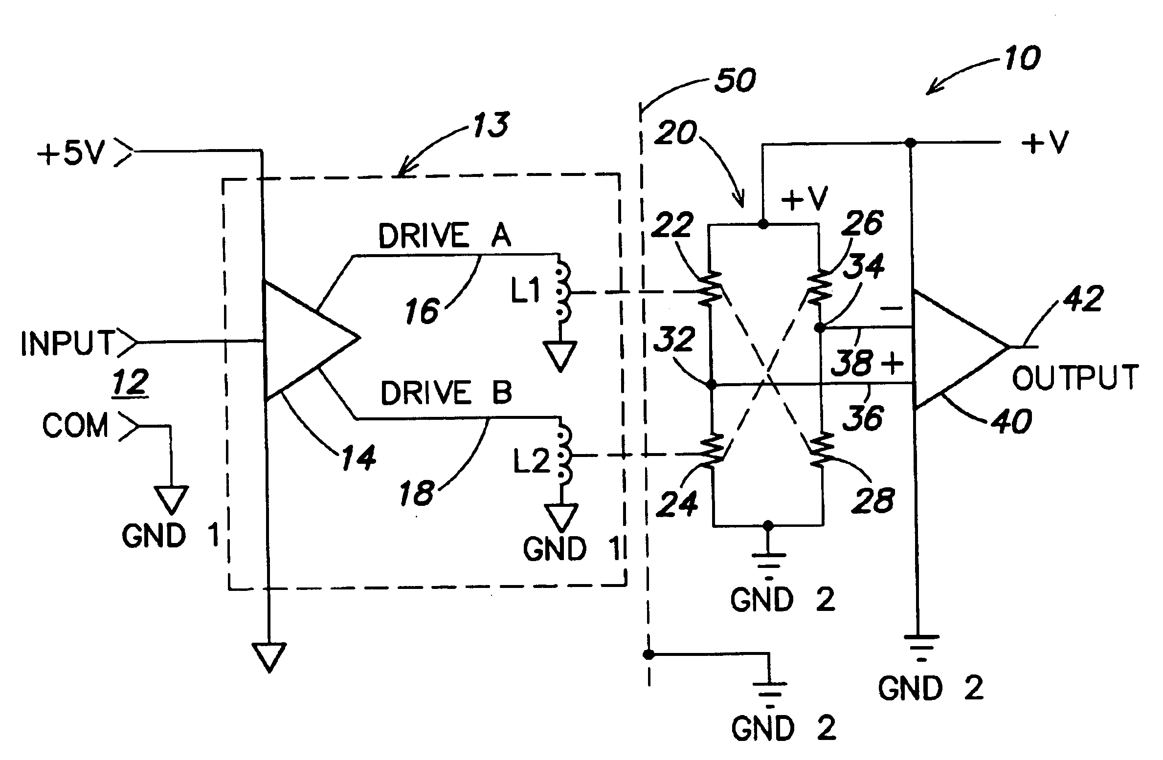
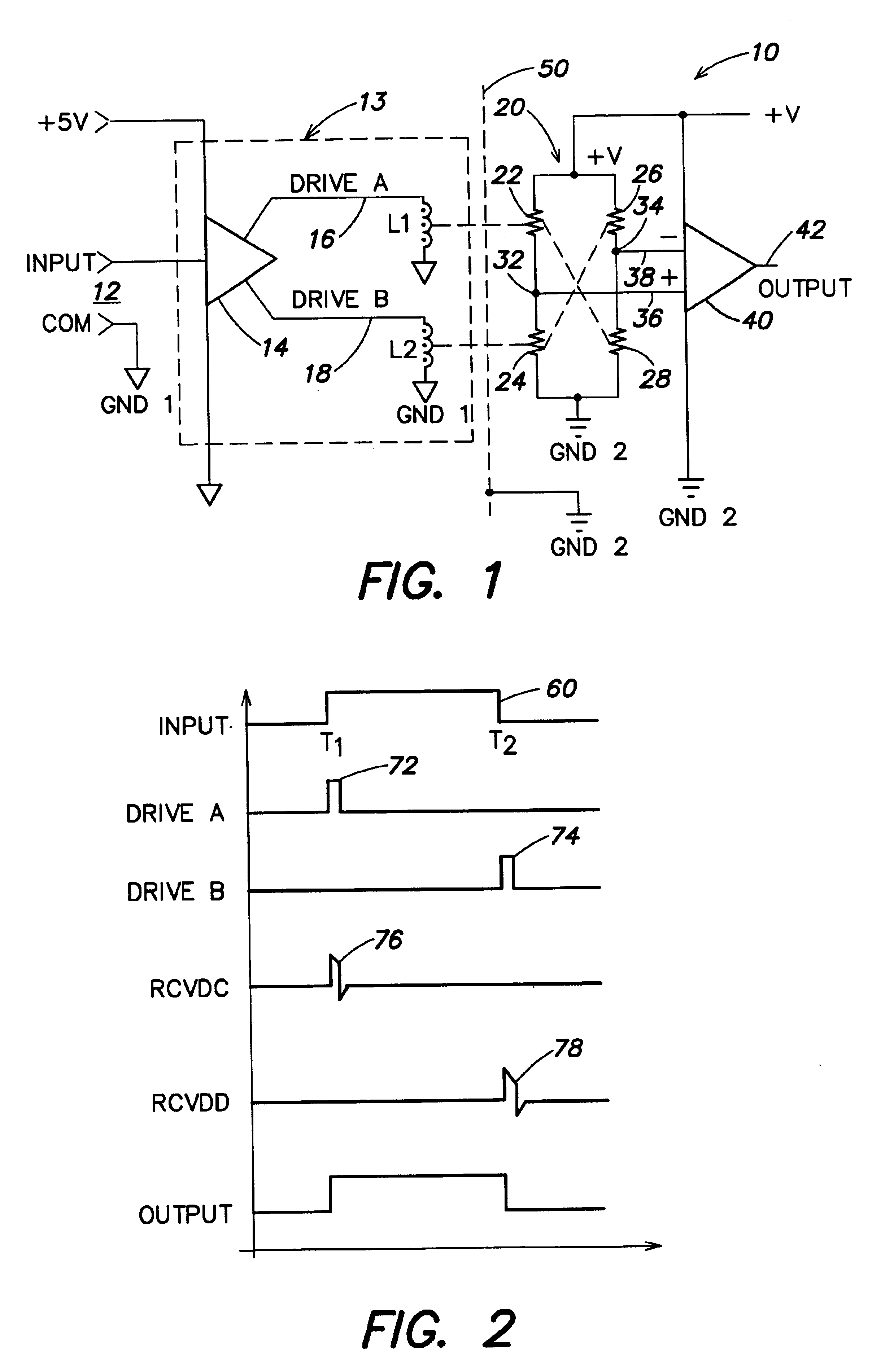
An exemplary implementation of an isolator 10 using coil-type field-generating and MR receiving elements in accordance with the present invention is illustrated schematically in FIG. 1. An input voltage is supplied at port 12 to a magnetic field generator 13, comprising an input driver 14 and one or more coils L1, L2. Driver 14 supplies output signals DRIVE A and DRIVE B on lines 16 and 18, respectively, to respective coils LI and L2. Each of coils L1 and L2 generates a magnetic field which is sensed by a bridge 20 formed by MR elements 22, 24, 26 and 28. Elements 22 and 24 are connected in series across the supply rails as are elements 26 and 28. The bridge provides a differential output across nodes 32 and 34 at the respective junctions between resistors 22 and 24 on the one hand, and 26 and 28 on the other. Node 32 supplies a first signal RCVDC on line 36 to a non-inverting input of a differential receiver 40 and node 34 supplies a second received signal RCVDD on line 38 to the i...


PUM


Abstract

A non-optical isolator having a driver circuit for providing an input signal to one or more first passive components which are coupled across a galvanic isolation barrier to one or more corresponding second passive components, and an output circuit that converts the signal from the second passive components to an output signal corresponding to the input signal. The entire structure may be formed monolithically as an integrated circuit on one or two die substrates, for low cost, small size, and low power consumption. The passive components may be coils or capacitor plates, for example. When the first and second passive components are capacitor plates, a Faraday shield may be provided between them, with the first and second passive components being referenced to separate grounds and the Faraday shield referenced to the same ground as the second passive components.

Description

FIELD OF THE INVENTIONThis invention relates to circuitry and structures for isolating electronic signals, such as signals in a process control system, or between microcontrollers and other signal sources and transducers or other devices using those signals.BACKGROUND OF THE INVENTIONIn a variety of environments, such as in process control systems, analog or digital signals must be transmitted between diverse sources and circuitry using those signals, while maintaining electrical (i.e., galvanic) isolation between the sources and the using circuitry. Isolation may be needed, for example, between analog sensors and amplifiers or other circuits which process their output, or between microcontrollers, on the one hand, and sensors or transducers which generate or use microcontroller input or output signals, on the other hand. Electrical isolation is intended, inter alia, to prevent extraneous transient signals, including common-mode transients, from inadvertently being processed as stat...

Claims


Application Information

Patent Timeline
Patent Type & Authority Patents(United States)
IPC IPC(8): H01L23/52H01L23/522H01L23/58H01L23/60H04B5/00
CPCH01L23/5222H01L23/5223H01L23/5227H01L23/60H04B5/00H04B5/0012H04L25/0266H01L2924/3025H01L2924/30107H01L2924/10253H01L25/16H01L23/645H01L2924/3011H04B5/0043H04B5/005H04B5/0093H01L2224/48137H01L2224/49175H01L23/552H01L23/642H01L2924/00H01L2224/05553H01L2924/00014H01L2224/05554Y02D30/70H01L2224/45099
Inventor HAIGH, GEOFFREY T.CHEN, BAOXING
Owner ANALOG DEVICES INC
Why Eureka
Try Eureka