Operation graph based event monitoring system

an event monitoring and graph technology, applied in the field of computer systems, can solve the problems of limited practical value, limited overall analysis, and only possible error analysis, and achieve the effect of facilitating and accelerating the process

Inactive Publication Date: 2005-03-29
INT BUSINESS MASCH CORP
View PDF6 Cites 12 Cited by
  • Summary
  • Abstract
  • Description
  • Claims
  • Application Information

AI Technical Summary

Benefits of technology

Thus, an object of the present invention is to provide efficient tracing of computer system operations in a computer system where a large variety of computer system operations is concurrently processed in a variety of system queues and buffers in the data flow.
The unique operation ID allows a trace of the course of a computer system operation even over chip boundaries and finally, the amount of data to be stored in a trace array is minimized by the generation of unambiguous, i.e. unique signatures for each possible course of an operation.

Problems solved by technology

During the course of operating a computer system, many types of computer operations can occur, for example, pressing of an enter key on a keyboard, loading of data from a disk into memory, or the occurrence of severe errors or further trace events.
However, after the hardware is available, error analysis is only possible with trace data that is generated by the hardware itself.
This location centric approach is, however, limited in its practical value because such methods are characterized by the facts that the sequence of operations can be analyzed only with a short history due to trace array limitations; further, the view of a trace is limited to a specific functional unit, i.e., a so-called “isolated view” limits the overall analysis, and finally, tracing is totally independent of error checking.
The control logic of this data flow is much more complex, making debugging of the behavior of such a system very difficult.
To be able to monitor and analyze the behavior of such a computer system, location centric monitoring as it is above is no longer sufficient because the complexity involved by the concurrent running of a plurality of operations hinders the analyzing user of the tracing system from gaining an overall analytical view of the system.

Method used


Image

  • Operation graph based event monitoring system
  • Operation graph based event monitoring system
  • Operation graph based event monitoring system

Examples


Embodiment Construction

The following is a very high level summary and discussion of present invention relative to the current state of the art in tracing.

The state-of-the art in tracing involves a three stage process:1. Observation2. Reduction3. Storing the reduced information

Steps 1 and 3 are generally trivial, the critical step being the reduction step.

An essential point is that the trace stores redundant information. The information is redundant in the sense that if the states of all of the latches are stored in every cycle in an ideal trace, then the information in the real trace would be a just a subset of the information in the ideal trace.

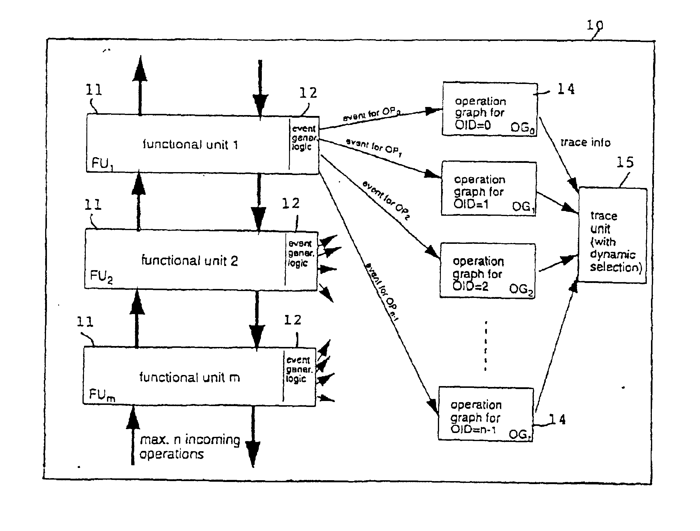
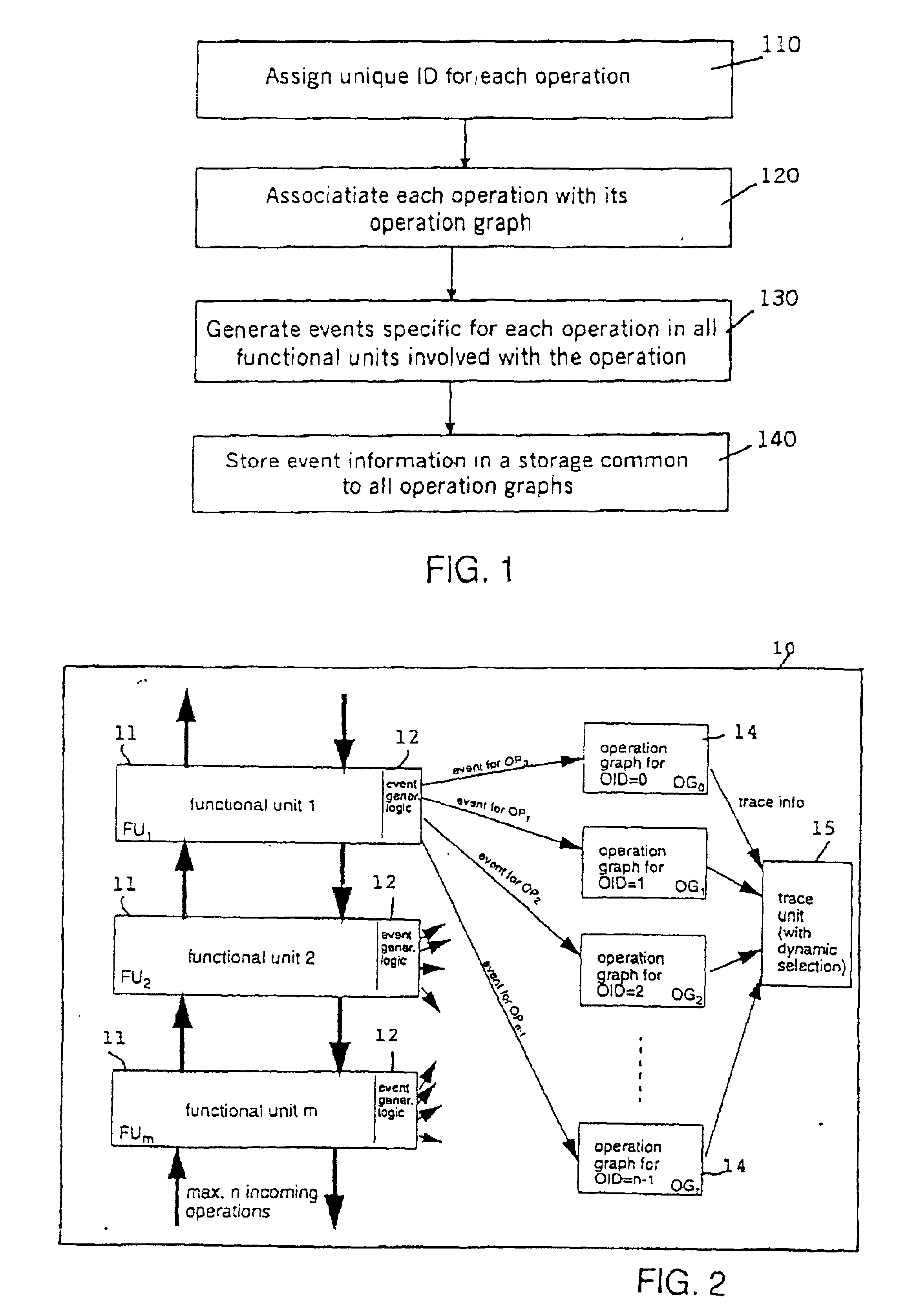
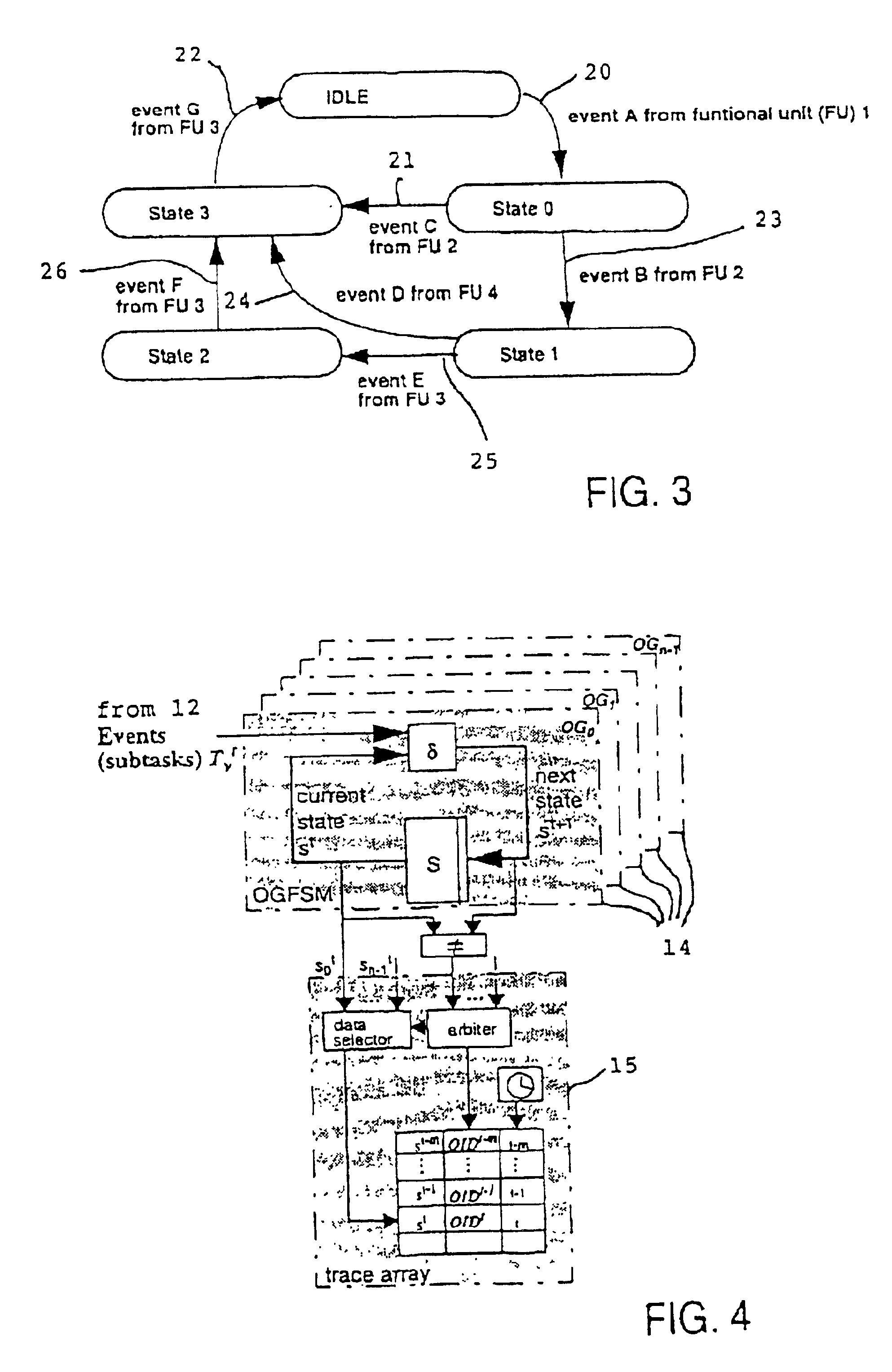
The present invention provides an operation graph associated with each traced computer operation which is not available even with an ideal trace. The operation graph is a language recognizer which recognizes the set of legal subtask execution sequences associated with each traced computer operation. In other words, the operation graph is a specification of all of ...


PUM


Abstract

A non-obtrusive activity monitor is proposed for advantageously monitoring and tracing disjunct, concurrent computer system operations in heavily queued computer systems. For each traced and pending computer system operation, the monitor uses a hardware implementation of an event triggered operation graph to trace the path of the computer system operation through the computer system. For each followed path, a unique signature is generated that significantly reduces the amount of trace data to be stored. In a preferred embodiment, the trace information is stored together with a time stamp for debugging and measuring queuing effects and timing behavior in a computer system.

Description

BACKGROUND OF THE INVENTION1. Field of the InventionThe present invention relates generally to hardware of computer systems, and more particularly pertains to a method and system for tracing system operations of a computer system.The present invention provides a non-obtrusive activity monitor for advantageously monitoring disjunct, concurrent computer operations in a heavily queued computer system. For each active computer operation, the activity monitor uses a hardware implementation of an event-triggered operation graph-monitoring device to trace the path of the computer operation through the computer system. For each operation, a unique signature is generated that records the actual path of the operation and significantly reduces the amount of trace data to be stored. In a preferred embodiment, the trace information is stored together with a time stamp for debugging and measuring queuing effects and timing behavior in the computer system.2. Discussion of the Prior ArtDuring the c...

Claims


Application Information

Patent Timeline
Patent Type & Authority Patents(United States)
IPC IPC(8): G06F11/00G06F9/44
CPCG06F11/3471G06F11/3447G06F2201/835G06F2201/86
Inventor BUECHNER, THOMASFRITZ, ROLFHELMS, MARKUS MICHAELLAMB, KIRK DAVIDSCHLIPF, THOMASWALZ, MANFRED H.
Owner INT BUSINESS MASCH CORP
Why Eureka
Try Eureka