Bi-rotational, two-stage hydraulic system

a hydraulic system and bi-rotational technology, applied in the field of hydraulic systems, can solve the problems of increasing the cost and complexity of separate systems, and requiring the cost and complexity of tilt cylinders and separate trim rams, so as to reduce the cost and complexity of the system, simple and compact system

Inactive Publication Date: 2005-05-03
PARKER INTANGIBLES LLC
View PDF8 Cites 29 Cited by
  • Summary
  • Abstract
  • Description
  • Claims
  • Application Information

AI Technical Summary

Benefits of technology

[0007]The present invention thereby provides an improved hydraulic system for an actuator, which provides staged (hi-low) operation, in both the ex

Problems solved by technology

As can be appreciated, the separate systems add cost, complexity and require significant space on the engine.
This reduces the cost and complexity of the system somewhat, but as can be appreciated, still requires the cost and complexity of a tilt cylinder and separate trim rams.
Since only a single pump is used, these systems also provide the exte

Method used


Image

  • Bi-rotational, two-stage hydraulic system
  • Bi-rotational, two-stage hydraulic system
  • Bi-rotational, two-stage hydraulic system

Examples


Embodiment Construction

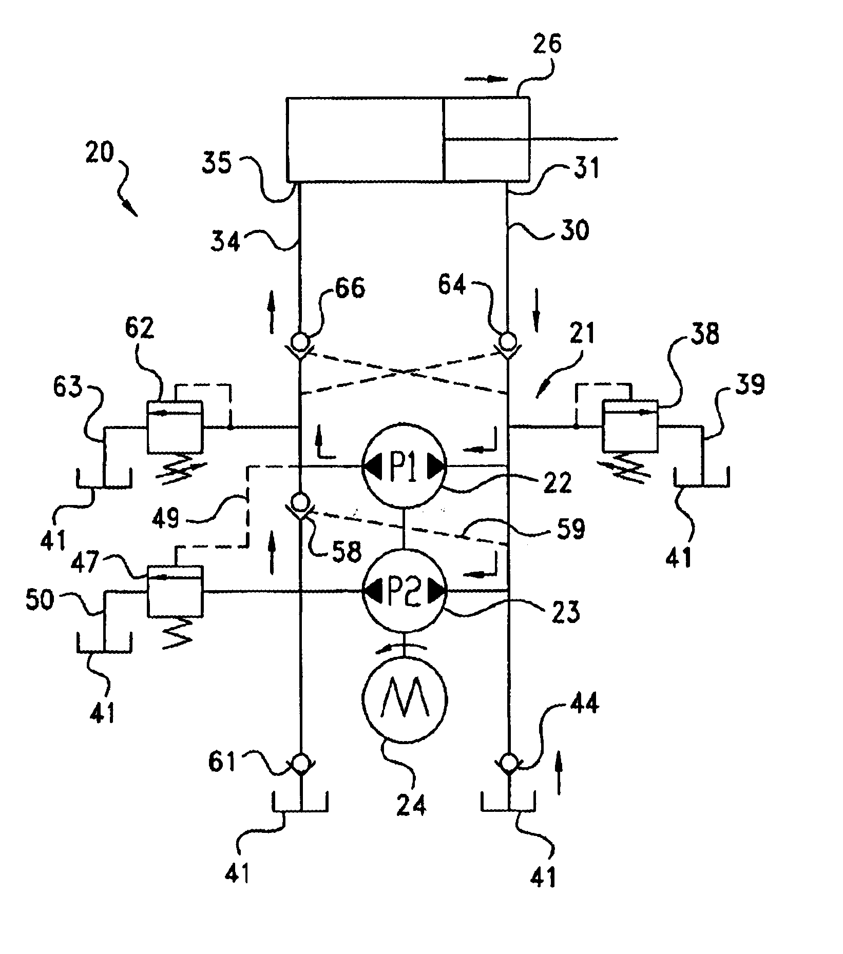
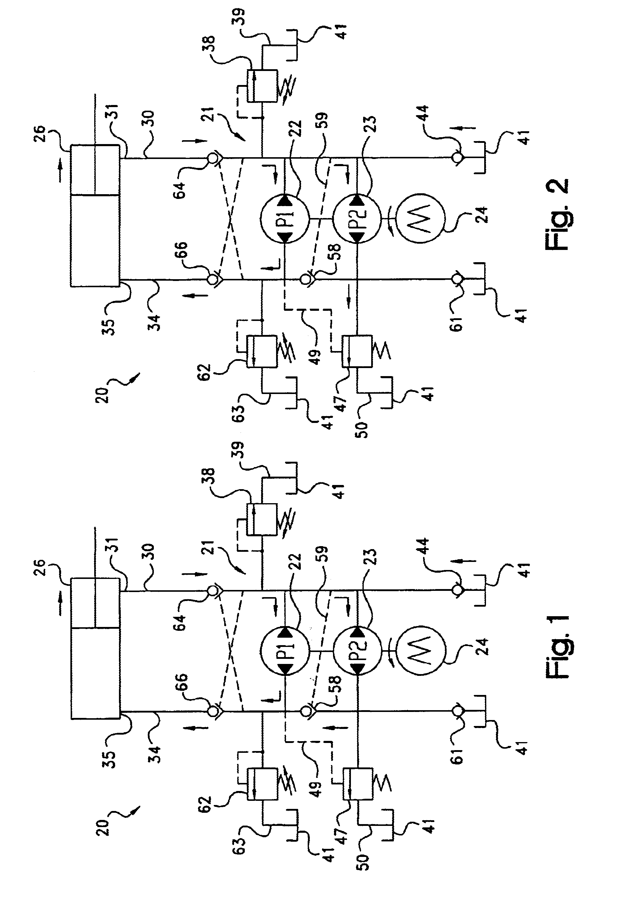
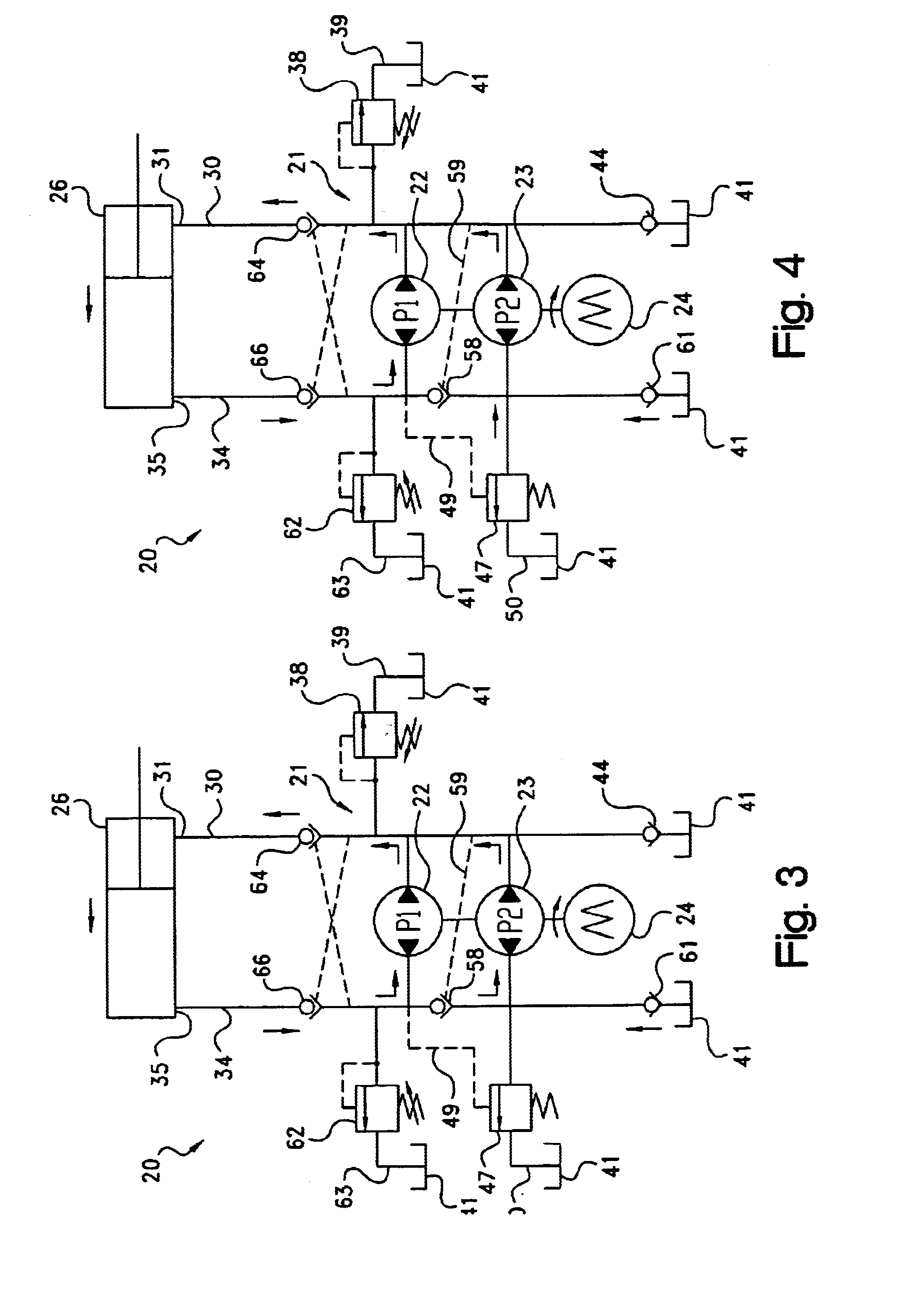
[0020]Referring to the drawings, and initially to FIGS. 1-4, a hydraulic system is illustrated generally at 20, including a pump assembly, indicated generally at 21, having a pair of bi-rotational first and second stage pumps 22, 23, connected for conjoint operation. The pumps are driven in both directions by a prime mover, i.e., a reversible motor 24. In one stage (FIGS. 1 and 3), flow from the two pumps is combined for high volume, low pressure and low load operation; while in another stage (FIGS. 2 and 4), flow from the second stage pump 23 is unloaded, and flow from the first stage pump 22 is used for low volume, high pressure and high load operation. The pump assembly is fluidly connected to an actuator such as a hydraulic cylinder 26. In one application, where the actuator is connected to an outboard marine engine (not shown), the first stage flow can be used to provide the trim function for the engine, while the second stage can be used to provide the tilt function for the en...


PUM


Abstract

A hydraulic system for an actuator provides staged operation during extend and retract. A pair of reversible pumps are conjointly driven by a reversible motor. A relief valve in the retract circuit directs fluid to tank when fluid pressure increases above a predetermined value. An unloader valve in the extend circuit is responsive to pressure at a first stage pump to direct flow to tank when the pressure increases above a second predetermined value. A non-return check valve connected between the pumps in the extend circuit closes the flow circuit to the second stage pump during high loads, so that the flow from the second stage pump goes to tank, and the return flow from the actuator goes only to the first stage pump. The non-return check valve is responsive (via a signal line to the retract circuit portion) to the pressure in the extend and retract circuit portions.

Description

CROSS-REFERENCE TO RELATED CASES[0001]The present application claims the benefit of the filing date of U.S. Provisional Application Ser. No. 60 / 354,354; filed Feb. 5, 2002, the disclosure of which is expressly incorporated herein by reference.FIELD OF THE INVENTION[0002]The present invention relates generally to hydraulic systems for controlling the operation of an actuator, such as a hydraulic cylinder.BACKGROUND OF THE INVENTION[0003]Actuators, such as hydraulic cylinders (also referred to as “hydraulic rams”), are used in a variety of applications to move or lift an object. Some of these are double-acting—meaning that they are designed to move a load in both the extend and retract directions. One particular application of this type of actuator is for the tilt and trim system for outboard marine engines. On many large outboard engines, two hydraulic rams perform the trim function (set the prop at a desired angle under thrust); while a separate cylinder performs the tilt function (...

Claims


Application Information

Patent Timeline
IPC IPC(8): F15B11/00F15B7/00F15B7/08F15B11/02B63H20/00B63H20/10F15B11/042
CPCF15B7/08F15B11/02F15B11/022F15B11/0426F15B7/006B63H20/10F15B2211/775F15B2211/20546F15B2211/20561F15B2211/20576F15B2211/30505F15B2211/3051F15B2211/50518F15B2211/50536F15B2211/5151F15B2211/528F15B2211/55F15B2211/7053
Inventor KUBINSKI, PAUL T.ANDERSON, DAVID J.
Owner PARKER INTANGIBLES LLC
Why Eureka
Try Eureka