Nozzle with flow equalizer

a technology of flow equalizer and nozzle, which is applied in the direction of fuel injecting pumps, machines/engines, lighting and heating apparatus, etc., can solve the problems of reducing the efficiency of combustion and the stability of flames, and reducing the complexity and cos

Inactive Publication Date: 2005-05-24
PARKER INTANGIBLES LLC
View PDF4 Cites 37 Cited by
  • Summary
  • Abstract
  • Description
  • Claims
  • Application Information

AI Technical Summary

Benefits of technology

[0009]The present invention provides a novel and unique fuel injector for a gas turbine engine of an aircraft, and more particularly, a novel and unique nozzle for a fuel injector. The nozzle provides substantially uniform spray for efficient combustion and stability of the flame; and has reduced complexity and cost as compared to prior designs.

Problems solved by technology

The recirculation zones are detrimental for total-pressure loses and heat transfer in the nozzle, as they increase the fuel residence time in the nozzle.
The spray from the nozzle also tends to have non-uniform distribution of fuel, which decreases the efficiency of combustion and the stability of the flame.
At high power (take-off) conditions, the fuel is highly turbulent and so these effects are somewhat reduced—but they are still an issue.
As can be appreciated, this requires additional cooperating structure between the adapter and nozzle, and complicates the manufacturing and assembly process.
The shoulder also has a relatively sharp edge, and if the edge is located too close to the surrounding fuel conduit, the edge can cause fuel separation and high pressure drop.
Thus, it is believed the shoulder in this nozzle design is not intended to provide significant fuel distribution around the circumference of the passageway, beyond what is provided by the upstream flange.

Method used


Image

  • Nozzle with flow equalizer
  • Nozzle with flow equalizer
  • Nozzle with flow equalizer

Examples


Embodiment Construction

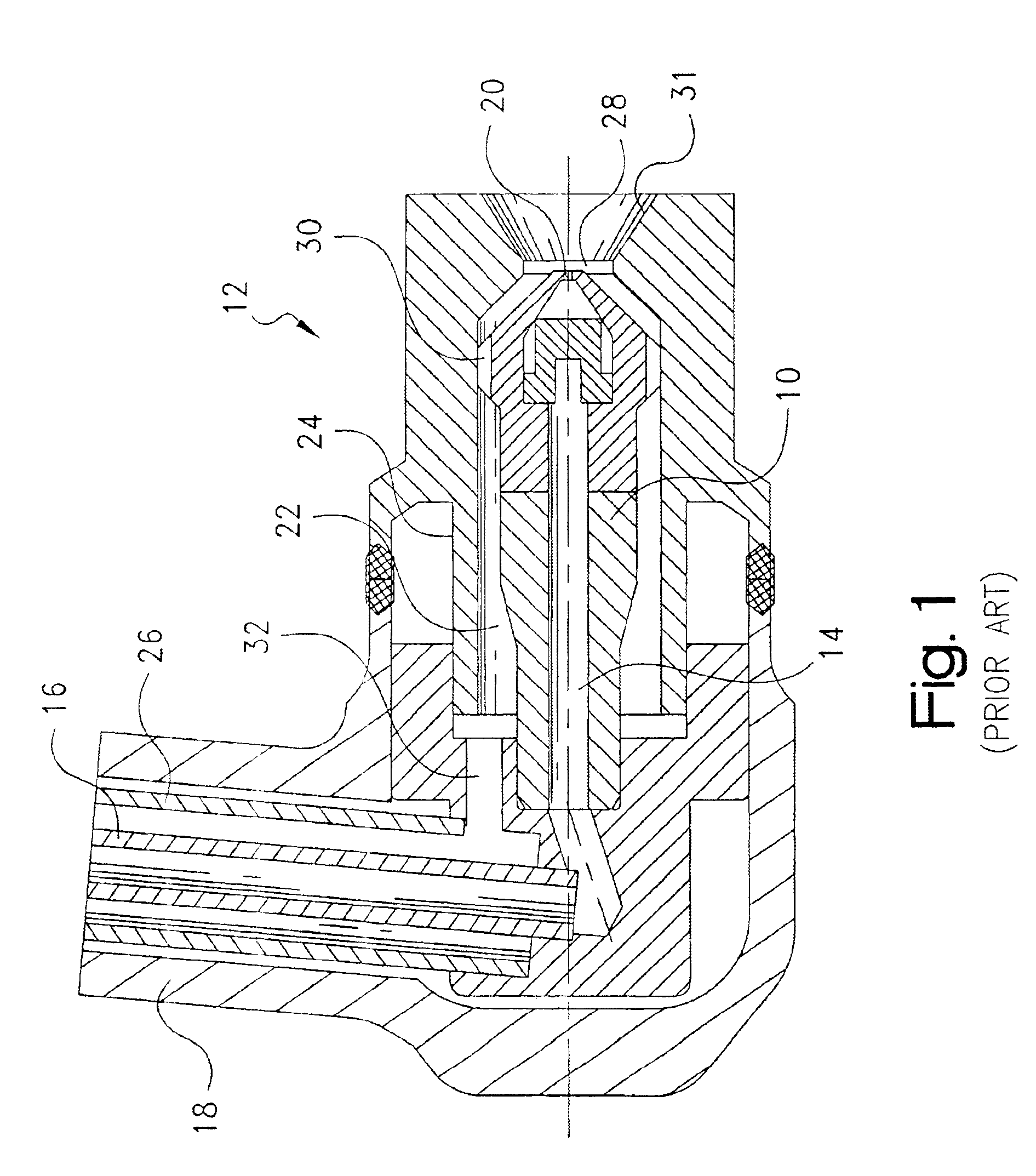
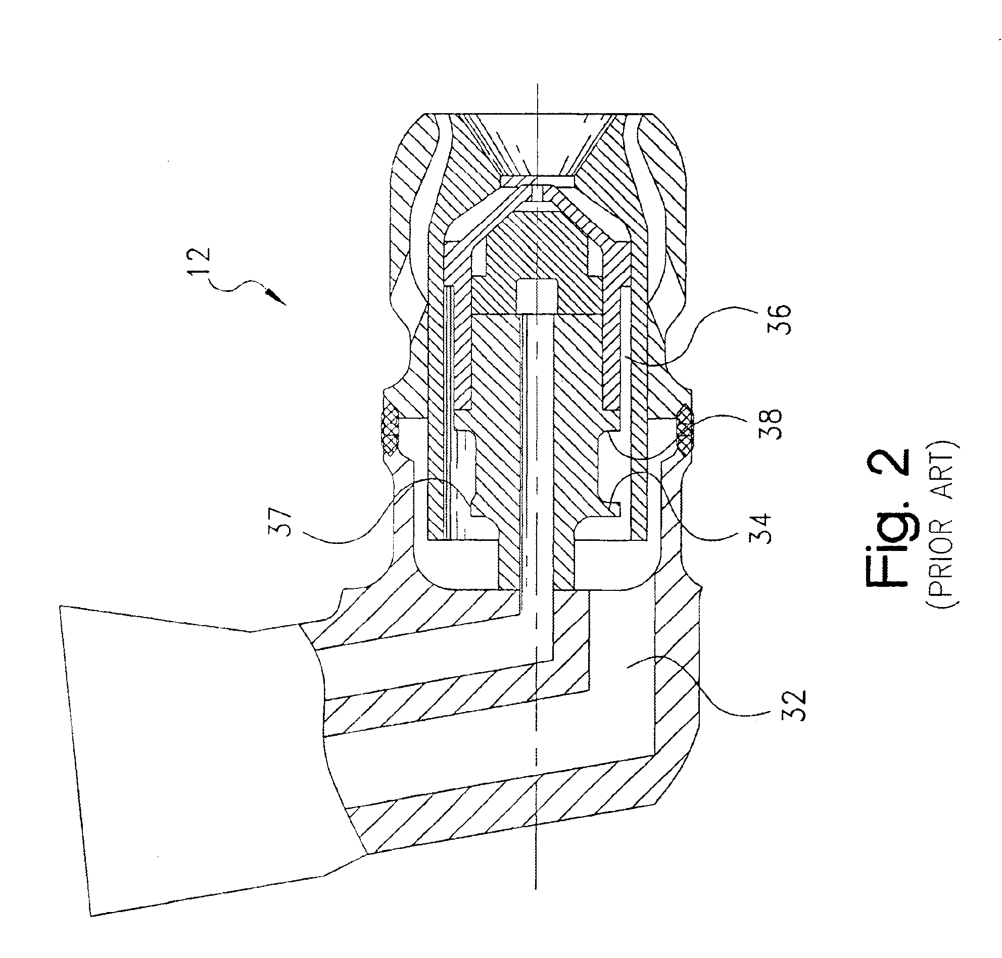
[0025]Referring to FIG. 3, a gas turbine engine for an aircraft is illustrated generally at 33. The gas turbine engine 33 includes an outer casing 34 extending forwardly of an air diffuser 35. The casing and diffuser enclose a combustor, indicated generally at 38, for containment of burning fuel. The combustor 38 includes a liner 40 and a combustor dome, indicated generally at 42. An igniter, indicated generally at 44, is mounted to casing 34 and extends inwardly into the combustor for igniting fuel. The above components are conventional in the art and their manufacture and fabrication are well known.

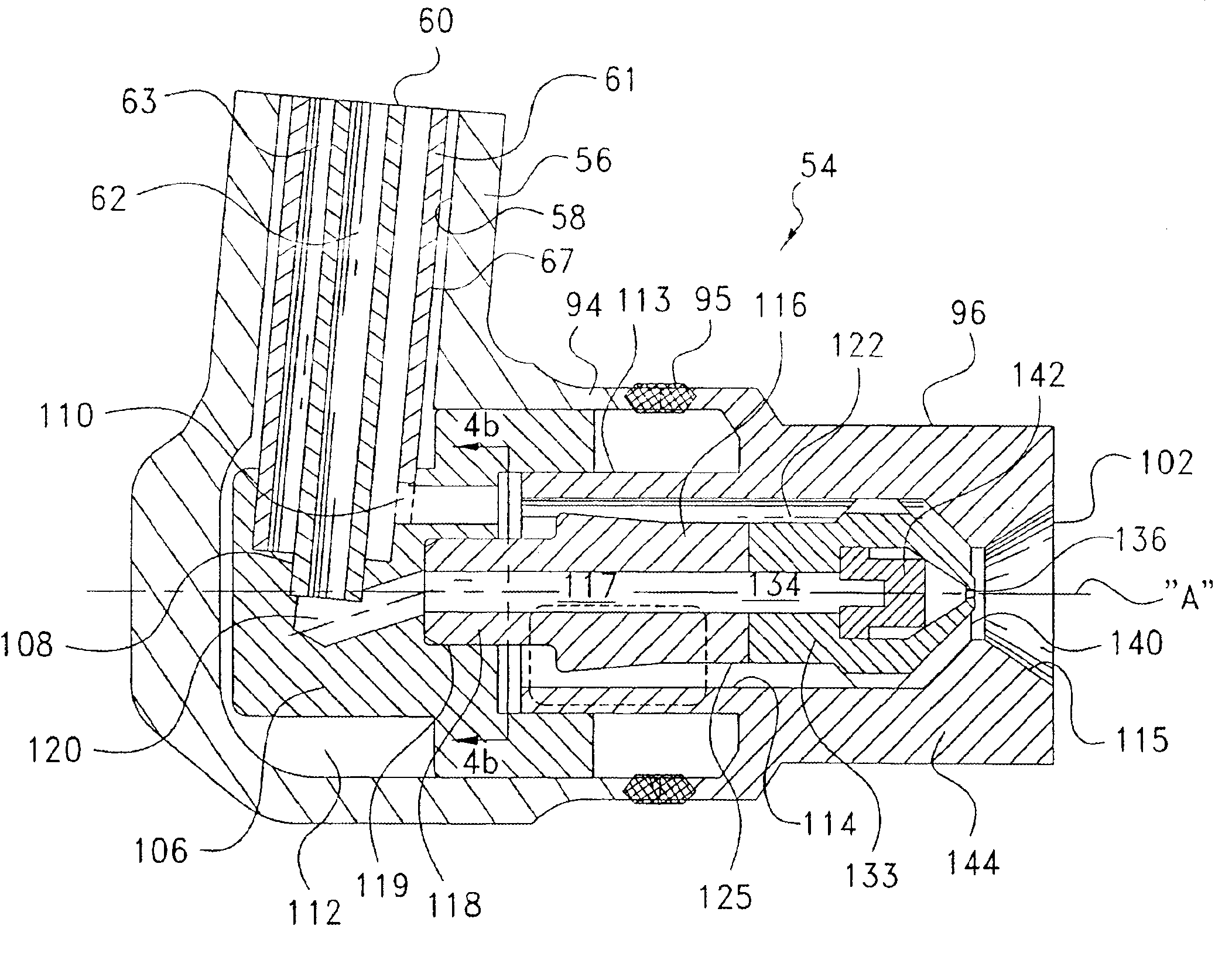
[0026]A fuel injector, indicated generally at 46, is received within an aperture 48 formed in the engine casing and extends inwardly through an aperture 50 in the combustor liner. Fuel injector 46 includes a fitting 52 disposed exterior of the engine casing for receiving fuel; a fuel nozzle, indicated generally at 54, disposed within the combustor for dispensing fuel; and a housing stem...


PUM


Abstract

A fuel injector for a gas turbine engine has an inlet fitting, a fuel nozzle, and a housing stem with a pair of fuel conduits fluidly interconnecting the nozzle and fitting. The fuel nozzle includes an annular secondary fuel passageway directing fuel from one fuel conduit to an annular discharge orifice at a discharge end of the nozzle. The secondary fuel passageway is defined between an outer, annular fuel conduit portion and a primary adapter. The primary adapter has an outer surface with a distinct, radially-outwardly-projecting annular shoulder to restrict flow through the secondary passageway and provide substantially uniform distribution of flow through the passageway downstream of the shoulder, for improved combustion and flame stability.

Description

CROSS-REFERENCE TO RELATED CASES[0001]The present application claims the benefit of the filing date of U.S. Provisional Application Ser. No. 60 / 361,508; filed Mar. 1, 2002, the disclosure of which is expressly incorporated herein by reference.FIELD OF THE INVENTION[0002]The present invention relates generally to fuel injectors for gas turbine engines of aircraft, and more particularly to nozzles for such fuel injectors.BACKGROUND OF THE INVENTION[0003]Fuel injectors for gas turbine engines on an aircraft direct fuel from a manifold to a combustion chamber. The fuel injector typically has an inlet fitting connected to the manifold for receiving the fuel, a fuel spray nozzle located within the combustion chamber of the engine for atomizing (dispensing) the fuel, and a housing stem extending between and supporting the fuel nozzle with respect to the fitting. Appropriate check valves and / or flow dividers can be disposed within the fuel nozzle to control the flow of fuel through the nozz...

Claims


Application Information

Patent Timeline
Patent Type & Authority Patents(United States)
IPC IPC(8): F23D11/10F23R3/28
CPCF23R3/28F23D11/107
Inventor STEINTHORSSON, ERLENDURPATWARI, KIRANQIAN, JIEQUADRONE, JOSEPH S.
Owner PARKER INTANGIBLES LLC
Why Eureka
Try Eureka