Wheelbarrow chute attachment

Inactive Publication Date: 2005-06-21
STARK TIMOTHY R +1
View PDF31 Cites 14 Cited by
  • Summary
  • Abstract
  • Description
  • Claims
  • Application Information

AI Technical Summary

Benefits of technology

[0004]The present invention provides a semi-enclosed pouring chute attachment for a wheelbarrow. The primary function of the invention attachment is to serve as an accuracy enhancing channeling device for materials being emptied from the wheelbarrow. The material could be solids, semi-solids, or liquids. The a

Problems solved by technology

However, none of these devices specifically address the need to ac

Method used


Image

  • Wheelbarrow chute attachment
  • Wheelbarrow chute attachment
  • Wheelbarrow chute attachment

Examples


Example

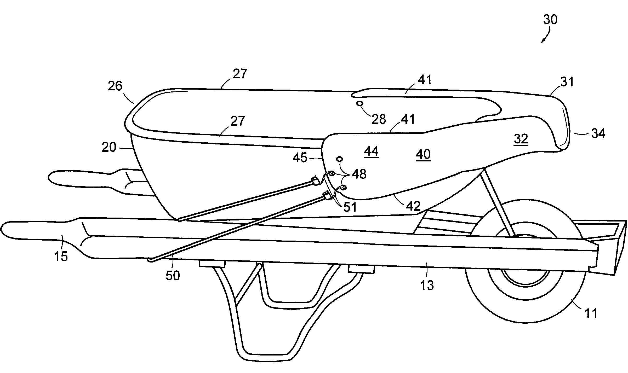
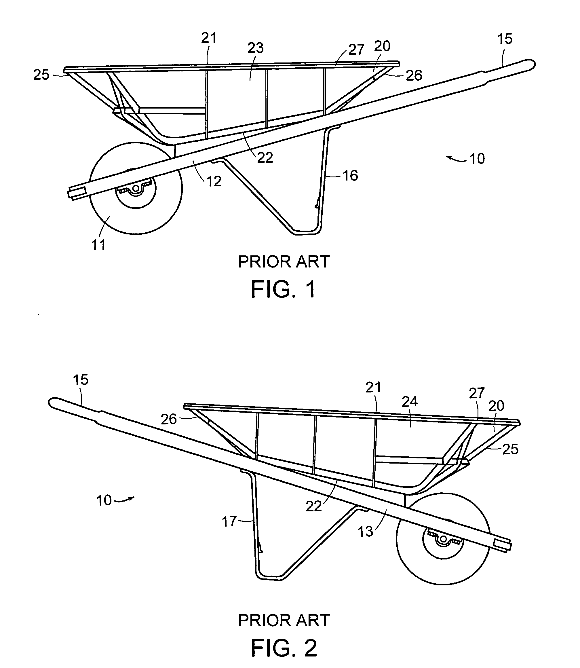
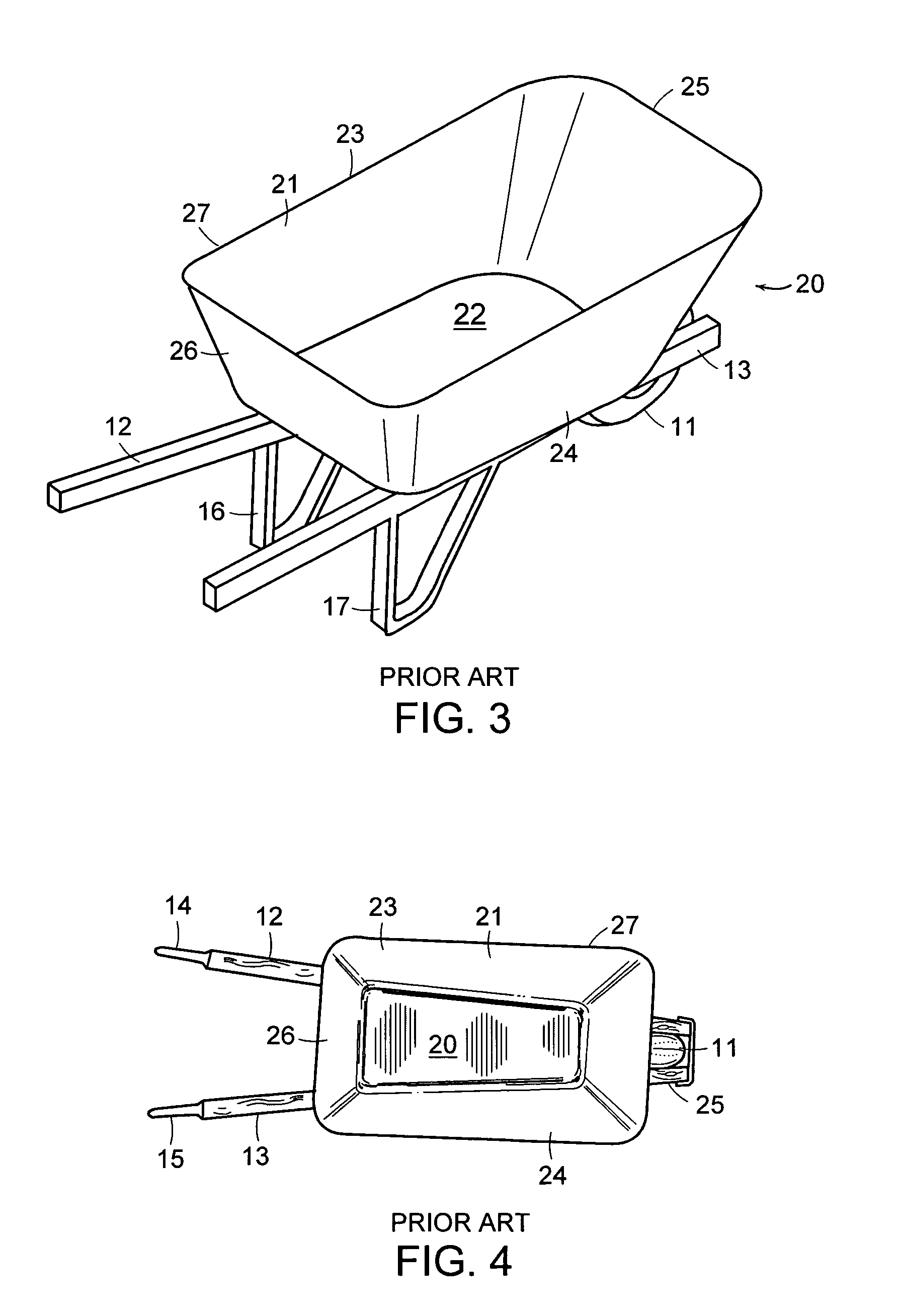
[0017]Referring to the drawings in detail wherein like elements are indicated by like numerals, especially FIGS. 1–4, reference numeral 10 generally represents a wheelbarrow having a front with a single forward wheel 11, two side frame pieces 12, 13 running in a rearwardly diverging manner from the front wheel 11, from which two handles 14, 15 are respectively extended and form a wheelbarrow rear, two rearward support legs 16, 17 each joined to a side frame piece 12, 13, respectively, at the back of the wheelbarrow in front of the handles 14, 15, and a container body 20 resting on the two side frame pieces 12, 13 behind the forward wheel 11 and in front of the handles 14, 15, said container body 20 having an open top 21, generally planar bottom 22 attached to said side frame pieces 12, 13, upwardly and outwardly inclined opposing sides 23, 24, an upwardly and outwardly inclined front end 25 and opposing rear end 26. The container body front end 25, rear end 26 and sides 23, 24 have ...


PUM


Abstract

A semi-enclosed pouring chute attachment for a wheelbarrow. The attachment sits on the front of the wheelbarrow and is secured by upper side channels and either rope of shock/bungee cords from the sides of the attachment to the handles of the wheelbarrow. In an alternate embodiment, the wheelbarrow container may have a funnel end as an integral part thereof.

Description

BACKGROUND OF THE INVENTION[0001]This invention relates to wheelbarrows, and in particular, to a semi-enclosed chute attachment for a wheelbarrow.[0002]There is a need both in home and commercial applications for a wheeled tool which allows one to transport bulky or heavy loads. The most commonly used tool to accomplish this purpose is called a wheelbarrow. A wheelbarrow is generally comprised of a forward wheel, a frame joined to and extending back from the wheel and terminating at the back of the wheelbarrow in handles which the user lifts to roll the wheelbarrow, two support legs joined to the frame at the back of the wheelbarrow in front of the handles, and a container resting on the frame. The container, also referred to as a tray or a tub, typically is roughly rectangular in shape. The front of the wheelbarrow container may be somewhat rounded. A wheelbarrow is usually unloaded by tipping vertically over the front wheel.[0003]Most wheelbarrows are designed to have the widest p...

Claims


Application Information

Patent Timeline
IPC IPC(8): B62B1/20
CPCB62B1/22B62B1/20
Inventor STARK, TIMOTHY R.WILLIAMSON, ALLAN B.
Owner STARK TIMOTHY R
Why Eureka
Try Eureka