Optical gas sensor device and method for determining the concentration of a gas

Active Publication Date: 2014-04-03
ROBERT BOSCH GMBH
View PDF0 Cites 11 Cited by
  • Summary
  • Abstract
  • Description
  • Claims
  • Application Information

AI Technical Summary

Benefits of technology

[0020]In a first exemplary variant, the light emission device may be a broadband light source that is designed for emitting light in a broadband spectral region that includes the measurement wavelength and the reference wavelength. In addition, the light detector may include two measuring channels and be designed for performing a measurement in the first measuring channel of an intensity of measurement light that has been reflected off of an object located in this spatial region, and for performing a measurement in the second measuring channel of an intensity of reference light that has been reflected off of an object located in the spatial region. This exemplary embodiment employs a broadband light source that may be relatively inexpensive.
[0021]The light source may include means for bundling the light emitted therefrom into the solid angle region. The bundling means may include a converging lens and/or a reflector device having an at least substantially concave reflector. In the solid angle region containing the reflecting object, the bundling means increase the intensity of the light incident to the object and, thus, the measurement light intensity measurable by the light detector, which, in turn, enhances the measurement accuracy in comparison to an exemplary embodiment that does not include bundling means.
[0022]The first measuring channel of the light detector may include a first filter device that is designed for essentially transmitting only light in a first narrowband measurement spectral region that essentially includes the measurement wavelength and not the reference wavelength. In addition, the second measuring channel of the light detector may include a second filter device that is designed for essentially transmitting only light in a second narrowband reference spectral region that essentially includes the reference wavelength and not the measurement wavelength. The filters block light that

Problems solved by technology

It is a characteristic of the known optical infrared gas sensors that, in spite of a sophisticated reflector device design, the entire absorption path is limited by the dimensions of the gas sensor.
Thin, portable

Method used


Image

  • Optical gas sensor device and method for determining the concentration of a gas
  • Optical gas sensor device and method for determining the concentration of a gas
  • Optical gas sensor device and method for determining the concentration of a gas

Examples


Example

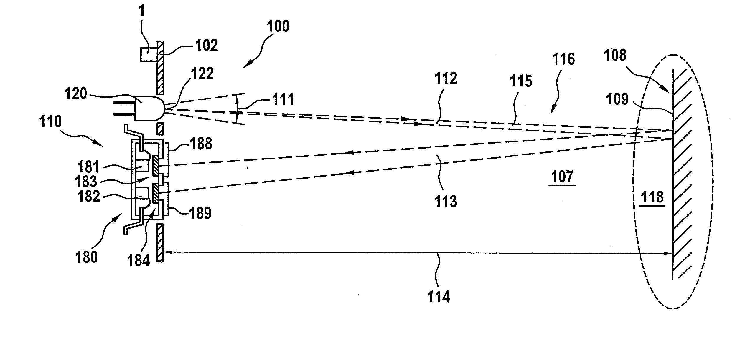
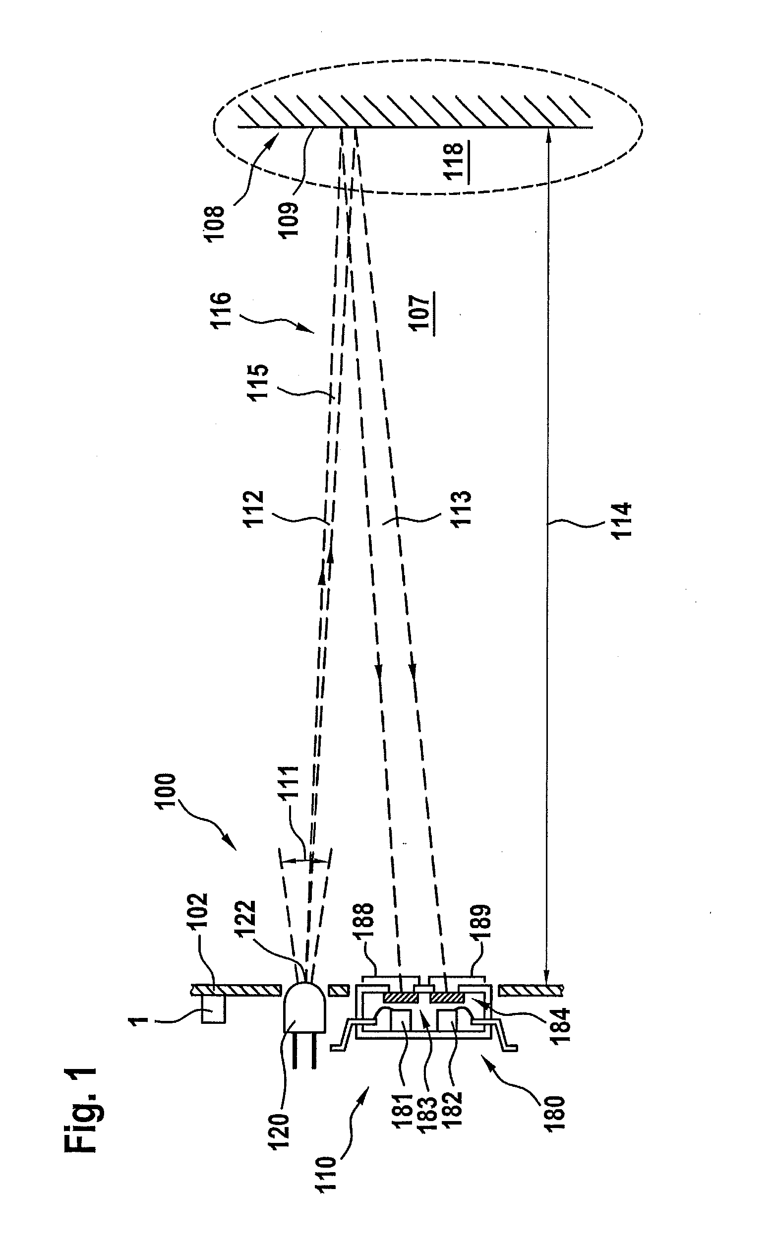
[0045]In the exemplary embodiment shown in FIG. 1, a gas sensor device 100 in accordance with the first exemplary variant of the first exemplary embodiment of the present invention includes a light emission device 110 that is designed for emitting measurement light of measurement wavelength λgas and reference light of reference wavelength λgas into a solid angle region 111 that encompasses a spatial region 118 located outside of gas sensor device 100, light detector 180 that is designed for measuring an intensity of measurement light that has been reflected off of an object 108 located in spatial region 118, and an intensity of reference light that has likewise been reflected off of object 108 located in spatial region 118. A bundle of rays 115 of light 116 emitted into solid angle region 111 traverses gas 107, initially along propagation path 112 from light emission device 110 to object 108, is partially reflected off of object 108, and again traverses gas 107 along propagation pat...


PUM


Abstract

A gas sensor device for determining a molar concentration of a gas to be detected, that absorbs light of a measurement wavelength that is characteristic of the gas in the infrared light region, includes a light emission device emitting measurement light of measurement wavelength into a solid angle region of a light absorption path extending through the gas, and a light detector measuring an intensity of at least one component of the measurement light that has propagated through the light absorption path, the light absorption path extending from the light emission device to an object outside the gas sensor device that at least partially reflects the measurement light to the light detector, and being essentially disposed outside of the gas sensor device, and means for determining the length of the light absorption path. A method for determining a concentration of a gas to be detected is also described.

Description

CROSS REFERENCE TO RELATED APPLICATION[0001]The present application claims priority to Application No. DE 10 2012 215 660.7, filed in the Federal Republic of Germany on Sep. 4, 2012, which is expressly incorporated herein in its entirety by reference thereto.FIELD OF INVENTION[0002]The present invention relates to an optical gas sensor device and to a method for determining the concentration of a gas.BACKGROUND INFORMATION[0003]Known gas sensors are mostly based on chemical or optical sensing principles. For the most part, optical sensing principles employ an absorption process, as summarized in FIG. 4. The known infrared optical gas sensor 2 shown exemplarily in FIG. 4 is based on the principle whereby, in a gas mixture, such as air, in which the concentration of a gaseous component is to be measured, for instance, the CO2− concentration in the air, the gaseous component to be measured absorbs light at a characteristic wavelength of λgas in the infrared spectral region. If, in the ...

Claims


Application Information

Patent Timeline
IPC IPC(8): G01N21/53
CPCG01N21/53G01S17/88G01N21/3504G01N2021/3513G01N21/314G01N2021/3137G01J1/0492G01J1/1626
Inventor SCHAEFER, FRANK
Owner ROBERT BOSCH GMBH
Why Eureka
Try Eureka