Step up/down converter

Active Publication Date: 2013-06-27
PANASONIC SEMICON SOLUTIONS CO LTD
View PDF3 Cites 11 Cited by
  • Summary
  • Abstract
  • Description
  • Claims
  • Application Information

AI Technical Summary

Benefits of technology

[0019]The load may contain a light emitting element. In addition, the load may include a light emitting element and a constant current source circuit connected in series with the light emitting element, and the first adjusting unit may be configured to detect a voltage of the constant current source circuit as the first detected voltage. Further, the first reference signal may be a voltage corresponding to a minimum voltage required for an operation of the constant current source circuit. This allows conducting the feedback control so that the first detection signal based on the output voltage is identical to the voltag

Problems solved by technology

Therefore, complicated circu

Method used


Image

  • Step up/down converter
  • Step up/down converter
  • Step up/down converter

Examples


Example

First Embodiment

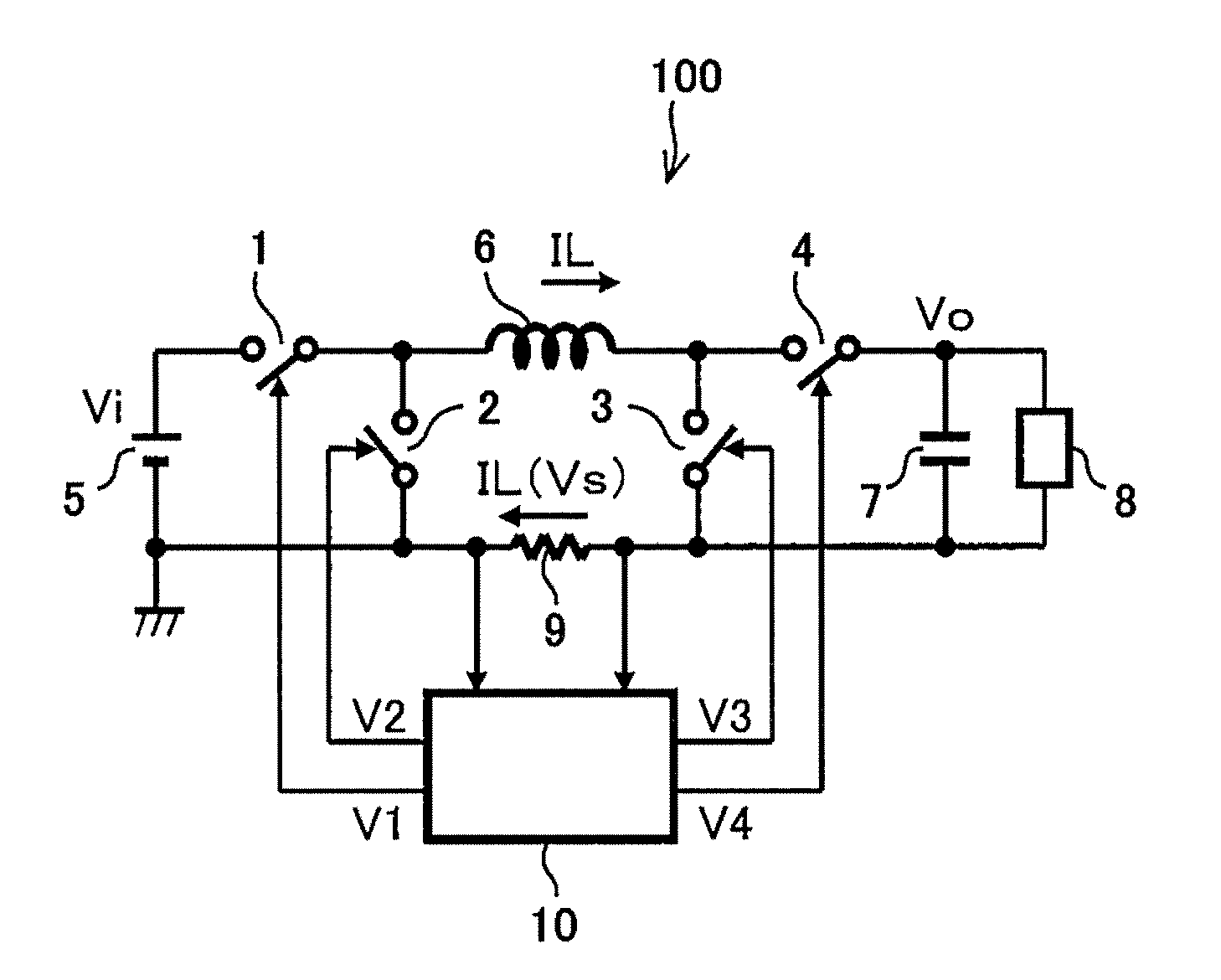
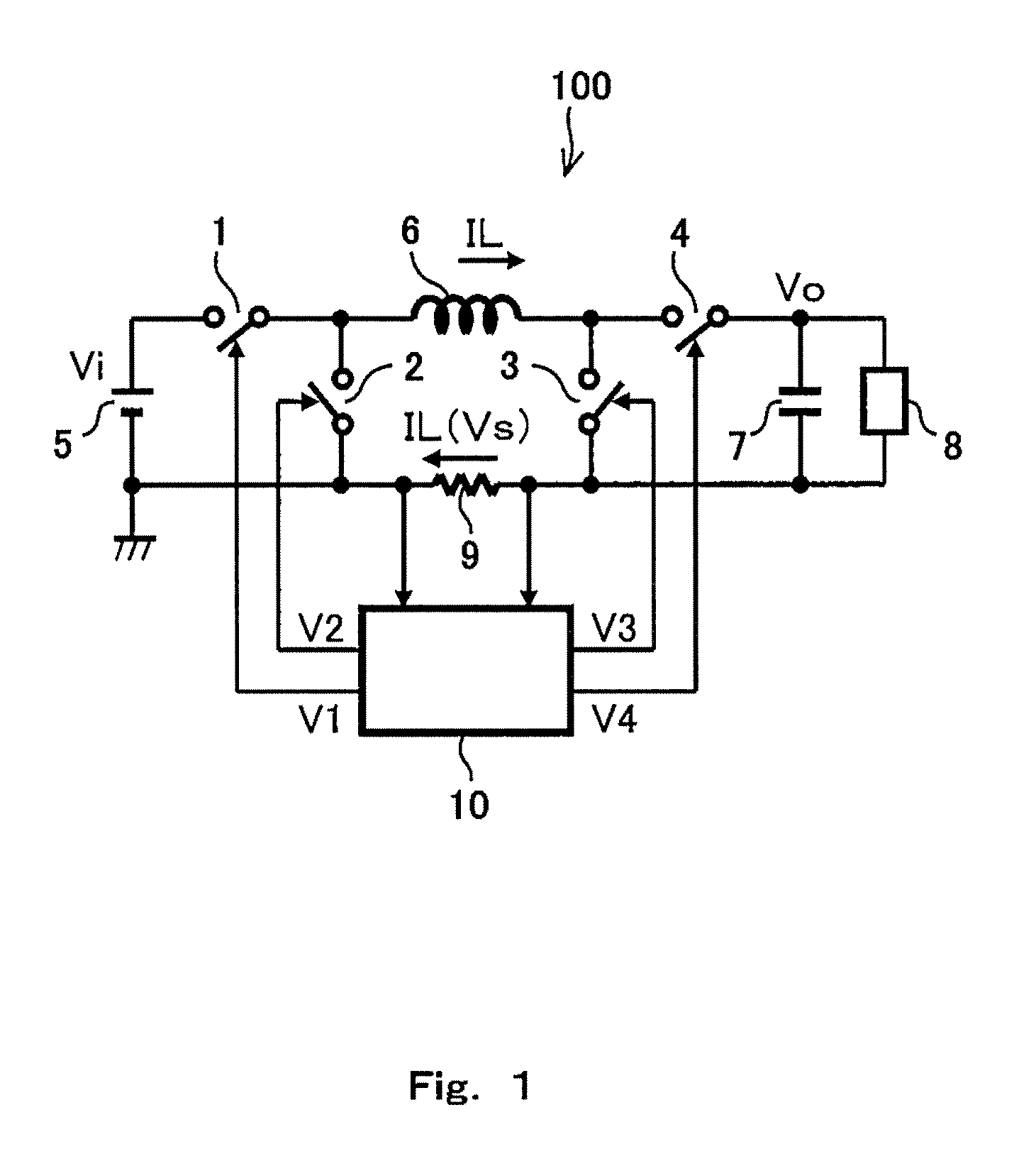
[0030]First of all, first embodiment of the present invention will be described. FIG. 1 is a circuit diagram, illustrating an exemplary schematic configuration of a step up / down converter according to first embodiment of the present invention. As shown in FIG. 1, a step up / down converter 100 of the present embodiment is connected to an input power source 5, which generates an input DC voltage Vi, in which a reference potential (ground potential in the present embodiment) is a reference. The step up / down converter 100 comprises four switches 1 to 4, an inductor 6 and a capacitor circuit element (output capacitor in the present embodiment) 7 to constitute and H bridge type step up / down converter. The step up / down converter 100 is configured to adjust an output voltage Vo (or output current) supplied to a load 8 connected to the output capacitor 7 by switching the respective switches 1 to 4 to cause a change of a mode for accumulating electric charge in the output capac...

Example

Second Embodiment

[0045]Next, second embodiment of the present invention will be described. FIG. 3 is a circuit diagram, illustrating an exemplary schematic configuration of a step up / down converter according to second embodiment of the present invention. In the present embodiment, the identical reference numeral is assigned to a configuration similar to that adopted in first embodiment, and further description is not presented. Features of a step up / down converter 100B of the present embodiment, which are different from the first embodiment, are that a control circuit 10B detects a first detection signal Vd1 based on an output voltage Vo and a driving signal is generated based on the first detection signal Vd1.

[0046]More specifically, the control circuit 10B includes: a first adjusting unit 31 for adjusting the first detection signal Vd1 based on the output voltage Vo to correspond to a signal level of a predetermined first reference signal (voltage) Vref1; a second adjusting unit 3...


PUM


Abstract

Provided is a step up/down converter, in which the inductor current can be easily detected by a simple configuration in any connecting mode of the switches. This comprises a first switch, one end of which is connected to an input power source, and the other end of which is connected to one end of the inductor, a second switch, one end of which is connected to the one end of the inductor, and the other end of which is connected to a reference potential applying unit, a third switch and a fourth switch, one end of which is connected to the other end of the inductor; a capacitor circuit element, connected between the other end of the third switch and the other end of the fourth switch, and configured to generate an output voltage for applying to a load, a detecting resistor, connected between the other end of the second switch and the other end of the third switch, and configured to detect an inductor current flowing through the inductor, and a control circuit configured to perform control from the first switch to the fourth switch based on the inductor current detected by the detecting resistor.

Description

CROSS REFERENCE TO RELATED APPLICATIONS[0001]This is a continuation application under 35 U.S.C 111(a) of pending prior International Application No. PCT / JP2012 / 001211, filed on Feb. 22, 2012.BACKGROUND OF THE INVENTION[0002]1. Field of the Invention[0003]The present invention relates to a step up / down converter for converting an input DC voltage from a power source into a predetermined DC voltage using an inductor, and supplies the predetermined DC voltage to a load, and particularly relates to a step up / down converter for controlling at a predetermined DC voltage based on an inductor current flowing through an inductor.[0004]2. Description of the Related Art[0005]In a step up / down converter, which converts an input DC voltage from a power source into a predetermined DC voltage by employing an inductor, and supplies it to a load, a configuration employing a H bridge circuit, in which inductor current flowing through an inductor is controlled by using four switches, is known (for exa...

Claims


Application Information

Patent Timeline
IPC IPC(8): G05F1/618H05B37/02H05B44/00
CPCH02M2001/0009G05F1/618H05B33/0818H05B37/02H02M3/1582H05B45/38H05B45/375H02M1/0009
Inventor ISHII, TAKUYAAZUMA, TAKESHI
Owner PANASONIC SEMICON SOLUTIONS CO LTD
Why Eureka
Try Eureka