Information entry device

a technology of information entry and pin, which is applied in the direction of static indicating devices, atm details, instruments, etc., can solve the problem of hard for someone to recognize pins

Inactive Publication Date: 2005-08-02
HABU TOMOHIRO
View PDF18 Cites 25 Cited by
  • Summary
  • Abstract
  • Description
  • Claims
  • Application Information

AI Technical Summary

Benefits of technology

[0015]In this case, again, the user can rotate the entry keys on the monitor screen before or after entering his PIN. By changing the locations of the keys by the rotation, it is possible to protect the PIN from being stolen by someone who tries to glance at the finger movement. Since the k

Problems solved by technology

Since the entire series of the keys is rotated, it is hard for someone to r

Method used


Image

  • Information entry device
  • Information entry device
  • Information entry device

Examples


first embodiment

[0025]the information entry device of this invention is explained below with reference to FIGS. 1-6.

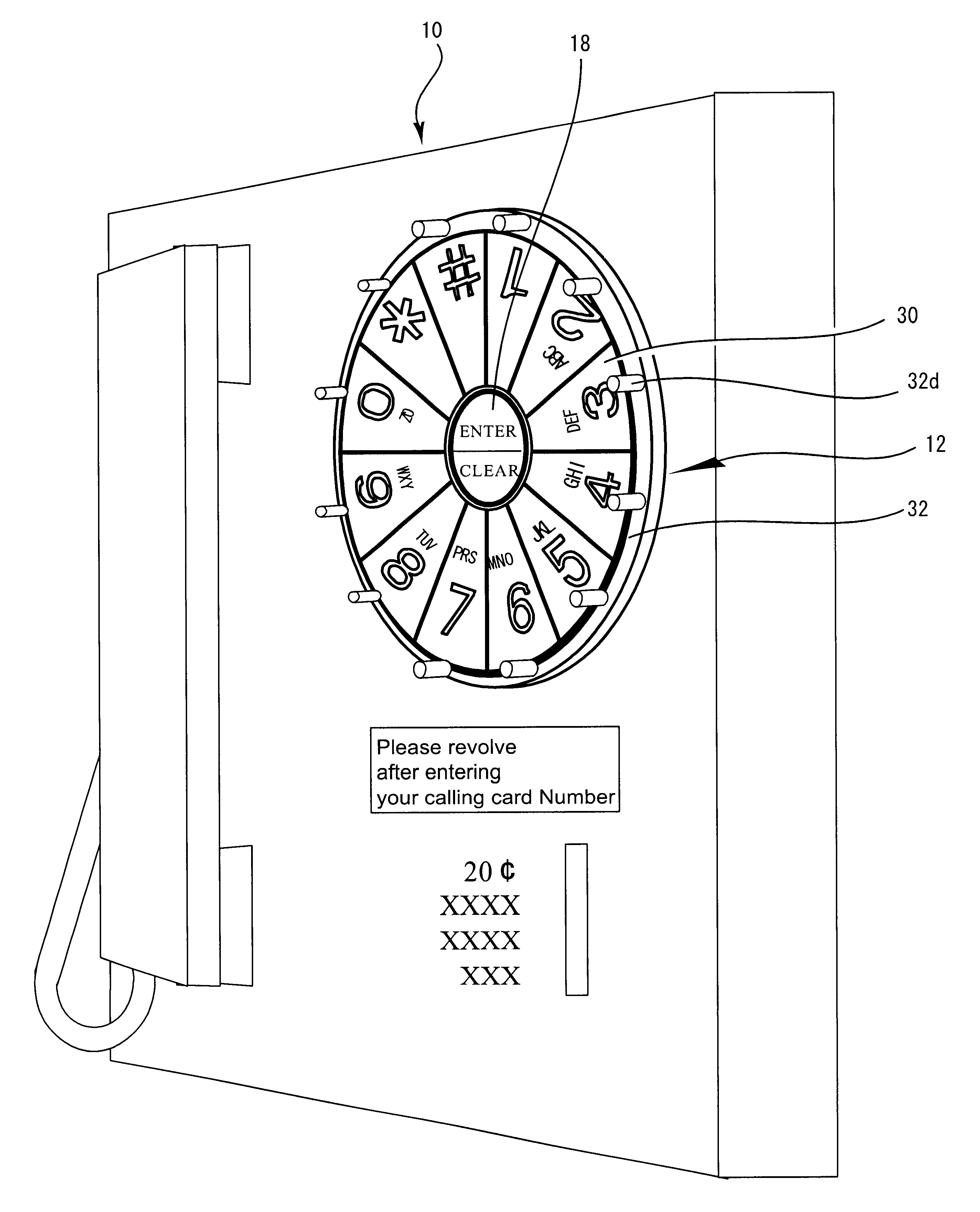
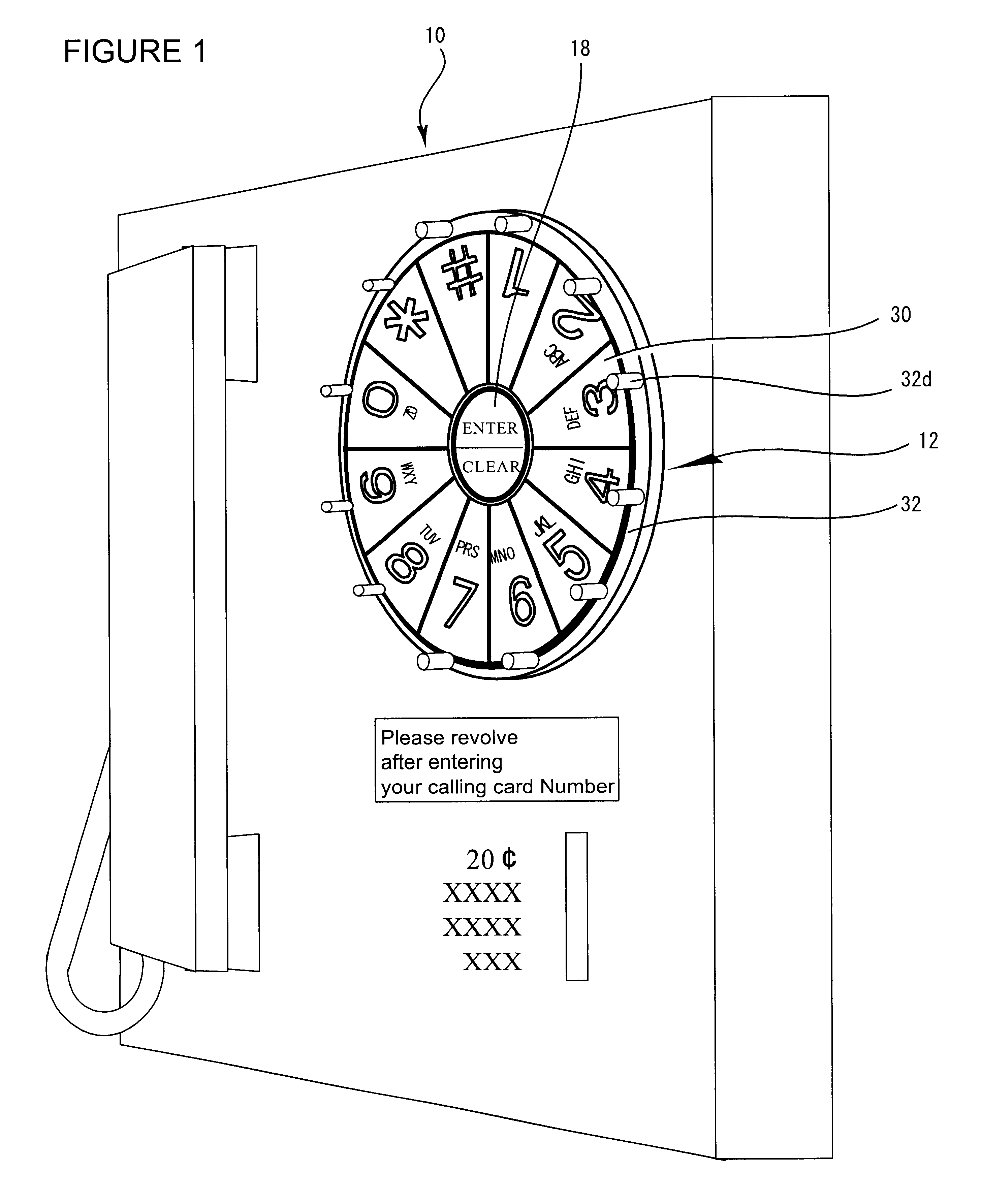
[0026]FIG. 1 is the perspective view of a public phone for which this device is adapted. The information entry device of this invention 12 is attached to the body of the public phone 10.

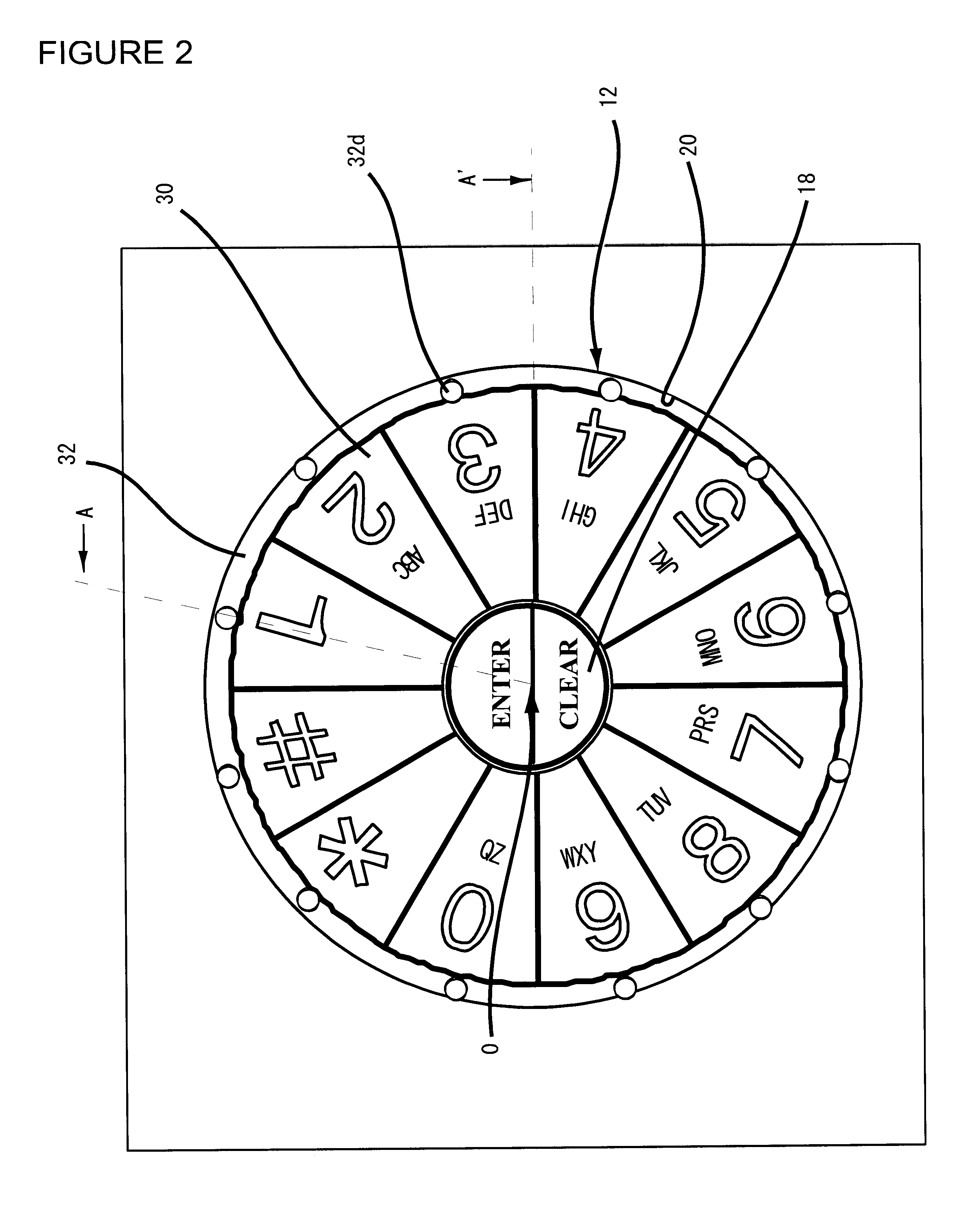
[0027]FIG. 2 is the expanded view from the front of the information entry device 12. In FIG. 3, the cross-sectional view along the line A-O and the cross-sectional view along the line A-O are shown side-by-side. A center button of “Enter / Clear”18 is installed on the body of the public phone 10 at the center of the information entry device 12. A groove 20 is concentrically provided around the center button 18 as shown in FIGS. 2 and 3. Each key 30 has a button comprising connection elements 34,36, and 38, which send the electronic signal when the button is pushed.

[0028]The information entry device 12 has the entry keys 30 and a circular support base 32 on which the entry keys are mounted. The support ba...

second embodiment

[0034]the information entry device of this invention is explained below with reference to FIGS. 7-9.

[0035]FIG. 7 is an overview of the touch panel screen of an ATM. This device has the touch panel 60 and a Central Processing Unit (CPU) 62. The CPU 62 recognizes the location touched on the touch screen monitor and controls the display on the touch screen monitor.

[0036]FIG. 8 shows the PIN entry screen of an ATM for which the information entry device of the present invention is adapted. The CPU 62 controls the touch screen monitor, which displays entry keys 66, an “Enter” button 68, a “Correct” button 70, a “Cancel” button 72, and a “Scramble” button 74. The twelve keys 66 have respective information of 0-9, # and *. These keys are circularly arranged in order. When the user touches the “Scramble” button 74, these entry keys 66 rotate in order and stop at some point. After the rotation of the keys, the CPU 62 obtains the rotation information by storing the number of key units shifted ...


PUM


Abstract

The objective of this invention is to protect the information entry such as a PIN from theft by observation of the finger movement based on the conventional fixed arrangement of entry keys.
The present invention is an information entry device including: keys for information entry; a circular support base on which the keys are mounted concentrically and arranged circularly in order, the support base being rotatable around the center of the circular arrangement for enabling a user to rotate the entire series of the mounted keys without changing their order around the center of the circular arrangement before or after the information entry; and an information discriminator for identifying the respective information of selected keys.
This information entry device prevents a PIN or any other information entry from being stolen by someone who glances at the finger movement, since the entire series of the entry keys are rotated before or after the PIN entry. The information entry device of the present invention can be adapted for an ATM or POS terminal as well as for a touch panel screen monitor.

Description

BACKGROUND OF THE INVENTION[0001]1. Technical Field of the Invention[0002]This invention relates to an information entry device, wherein provision is made for protecting the information entry such as a PIN from being stolen.[0003]2. Description of Prior Art / Current Technology[0004]Various kinds of financial transaction services are provided by using IT (Information Technology) these days, such as credit cards, debit cards, digital wallets by use of smart cards and so on. Information of the card is kept in the magnetic stripe or IC chip of the card. Also, we can now use a public phone by entering a call card number instead of inserting a coin.[0005]To use these services, a PIN or password entry is required for user identification. Nowadays using a credit card requires signature. But when a smart card is used for a credit card instead of a magnetic stripe, it requires a PIN entry. The arrangement of keys of a PIN pad on an ATM and the like is specified in ISO 9564-1 Annex-E This speci...

Claims


Application Information

Patent Timeline
IPC IPC(8): G06F3/033G06F21/00G06F3/023G06F3/048G07F7/10H04M1/23
CPCG06F3/0219G06F3/0488G06F21/83G07F7/10G07F7/1041G07F19/201H04M1/23
Inventor HABU, TOMOHIRO
Owner HABU TOMOHIRO
Why Eureka
Try Eureka