Circuit for maintaining hold-up time while reducing bulk capacitor size and improving efficiency in a power supply

a technology of bulk capacitors and power supply, which is applied in the direction of electric variable regulation, process and machine control, instruments, etc., can solve the problems of significant efficiency drop, inability to operate over a very wide duty cycle, and inability to meet the requirements etc., to achieve the effect of improving the efficiency of dc to dc converters, reducing the operating range of input voltage, and reducing peak current and voltage stresses

Inactive Publication Date: 2006-06-13
ASTEC INT LTD
View PDF4 Cites 118 Cited by
  • Summary
  • Abstract
  • Description
  • Claims
  • Application Information

AI Technical Summary

Benefits of technology

[0025]Another advantage of the present invention is that it improves the efficiency of the DC to DC converter by reducing its input voltage operating range.
[0026]Another advantage of the present invention is that it reduces the peak current and voltage stresses on the DC to DC converter components.
[0027]Another advantage of the present invention is that it reduces the size of the output filter components because of a higher steady state duty cycle.

Problems solved by technology

Other topologies, such as the forward converter, cannot operate over a very wide duty cycle since, for very wide duty cycle variations, the efficiency drops significantly due to high peak currents.
This significant drop in efficiency limits the practical input voltage tolerance of the DC to DC converter.
As a result, for forward converters and other topologies that cannot operate over a very wide duty cycle, only a limited amount of energy stored in the bulk capacitor C1 is utilized during a power failure mode.
This results in inefficient use of the available space in the power supply, affecting the power density.
However, the size of the bulk capacitor still remains the same, and this severely restricts advancements in higher power density.
A drawback of power converter 20 in FIG. 2 is that the additional buck converter operates continuously and dissipates power.
Another drawback of power converter 30 is that it requires an extra storage capacitor C2 which must be large enough to store enough energy to provide the required additional hold-up time.
Still another drawback of power converter 30 is that it does not reduce the operational range of the DC to DC converter less than for other prior art converters.
As a result, power converter 30 does not provide any performance gain over prior art converters.
One drawback of the circuit in FIG. 5 is that capacitor C1 fails to provide the larger hold-up time required in most applications.
As a result, there is poor energy utilization in this example.
However, such a circuit would still have the drawbacks described above with respect to converter 10.

Method used


Image

  • Circuit for maintaining hold-up time while reducing bulk capacitor size and improving efficiency in a power supply
  • Circuit for maintaining hold-up time while reducing bulk capacitor size and improving efficiency in a power supply
  • Circuit for maintaining hold-up time while reducing bulk capacitor size and improving efficiency in a power supply

Examples


Embodiment Construction

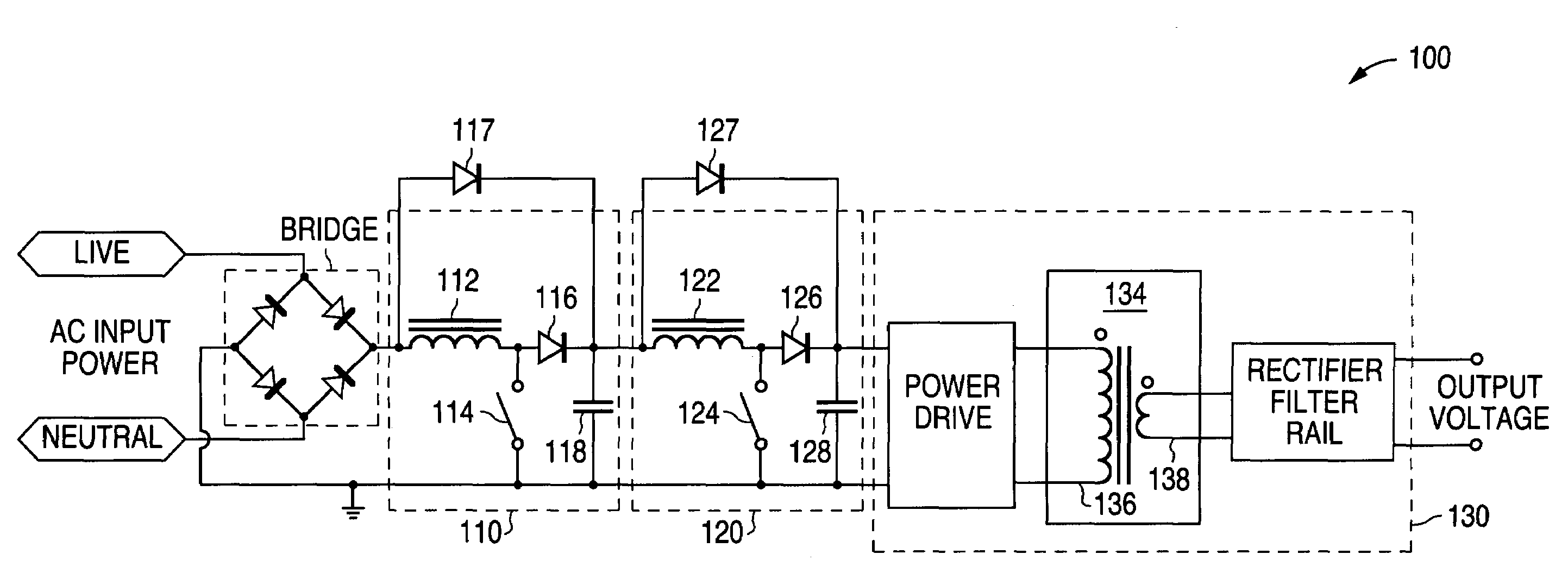
[0038]A preferred embodiment of a circuit according to the present invention is shown at 100 in FIG. 6. Converter 100 includes a first stage boost converter 110, a downstream DC to DC converter 130, and a second stage converter 120 inserted between the first stage boost converter 110 and the DC to DC converter 130. A rectified input AC voltage is boosted by the first stage boost converter 110, comprising an inductor 112, a switch 114, a diode 116, and a bulk capacitor 118. The first stage boost converter 110 provides a boosted bulk voltage across capacitor 118. The second stage converter 120 of converter 100 is preferably a boost converter comprising an inductor 122, a switch 124, a diode 126, and a decoupling capacitor 128. As shown in FIG. 6, the DC to DC converter 130 is coupled between the output and the second stage boost converter 120. The downstream DC to DC converter 130 includes a conventional power drive circuit coupled between the second stage boost converter 120 and the ...


PUM


Abstract

A circuit that utilizes most of the energy stored in the bulk capacitor of an AC to DC or DC to DC converter power supply by providing an intermediate converter between a first stage boost converter and a DC-DC converter. When the bulk voltage starts to fall during the hold-up time, the intermediate converter boosts the falling voltage to maintain the regulated DC input to the DC to DC converter while reducing the operating range and increasing the operating duty cycle, so as to increase efficiency, reduce peak current and voltage stresses. The circuit also reduces the size of the output filter components and reduces the size of the bulk capacitance by up to half.

Description

RELATED APPLICATIONS[0001]This application claims the priority of U.S. Provisional Application No. 60 / 493,537, filed on Aug. 8, 2003, entitled “A Circuit for Maintaining Hold-Up Time While Reducing Bulk Capacitor Size and Improving Efficiency in a Power Supply”.FIELD OF INVENTION[0002]The present invention relates in general to power converter circuits and more particularly to a circuit that utilizes a boost converter front end to provide power factor correction.BACKGROUND OF INVENTION[0003]A conventional AC to DC power converter typically includes a boost converter front end for power factor correction of the input bulk voltage generated from the AC input power source and a downstream DC to DC converter to convert the unregulated bulk voltage into an output voltage that satisfies the voltage regulation and transient response requirements of the power converter. In most applications, there is a “Power Hold-up” requirement for such converters. In other words, the DC output voltage ge...

Claims


Application Information

Patent Timeline
Patent Type & Authority Patents(United States)
IPC IPC(8): G05F1/656G05F1/652H02M1/00H02M1/42H02M3/28
CPCH02M1/4225H02M3/28Y02B70/126H02M2001/0096H02M2001/007Y02B70/10H02M1/007H02M1/0096
Inventor PHADKE, VIJAY GANGADHAR
Owner ASTEC INT LTD
Why Eureka
Try Eureka