Liquid crystal display device and driving method thereof

a technology of liquid crystal display device and driving method, which is applied in the direction of static indicating device, cathode-ray tube indicator, instruments, etc., can solve the problem of bringing about unnecessary cost, and achieve the effect of reducing low-frequency sound

Inactive Publication Date: 2006-07-25
SHARP KK
View PDF6 Cites 3 Cited by
  • Summary
  • Abstract
  • Description
  • Claims
  • Application Information

AI Technical Summary

Benefits of technology

[0013]An object of the present invention is to provide a liquid crystal display device capable of reducing a low-frequency sound caused by piezoelectricity of a liquid crystal capacitance, and a driving method thereof.

Problems solved by technology

However, the conventional method to insert the tantalum condenser between the counter electrode driving signal and the ground terminal or to cover the panel surface with the housing has the following problems.
For example, this brings about an unnecessary cost, and, since this does not remove the fundamental cause of the low-frequency sound, the low-frequency sound occurs again when an operating frequency is varied in the liquid crystal display device.
Further, the Patent Publication 1 does not describe a method to reduce the sounding from a viewpoint of circuitry.

Method used


Image

  • Liquid crystal display device and driving method thereof
  • Liquid crystal display device and driving method thereof
  • Liquid crystal display device and driving method thereof

Examples


Embodiment Construction

[0031]The following will explain an embodiment of the present invention with reference to FIGS. 1 through 6. Note that, the present embodiment will explain an example in which a matrix liquid crystal display device uses a TFT (thin film transistor) as an active element, but the present invention can be applied to a liquid crystal display device using any active element (two-terminal element, for example).

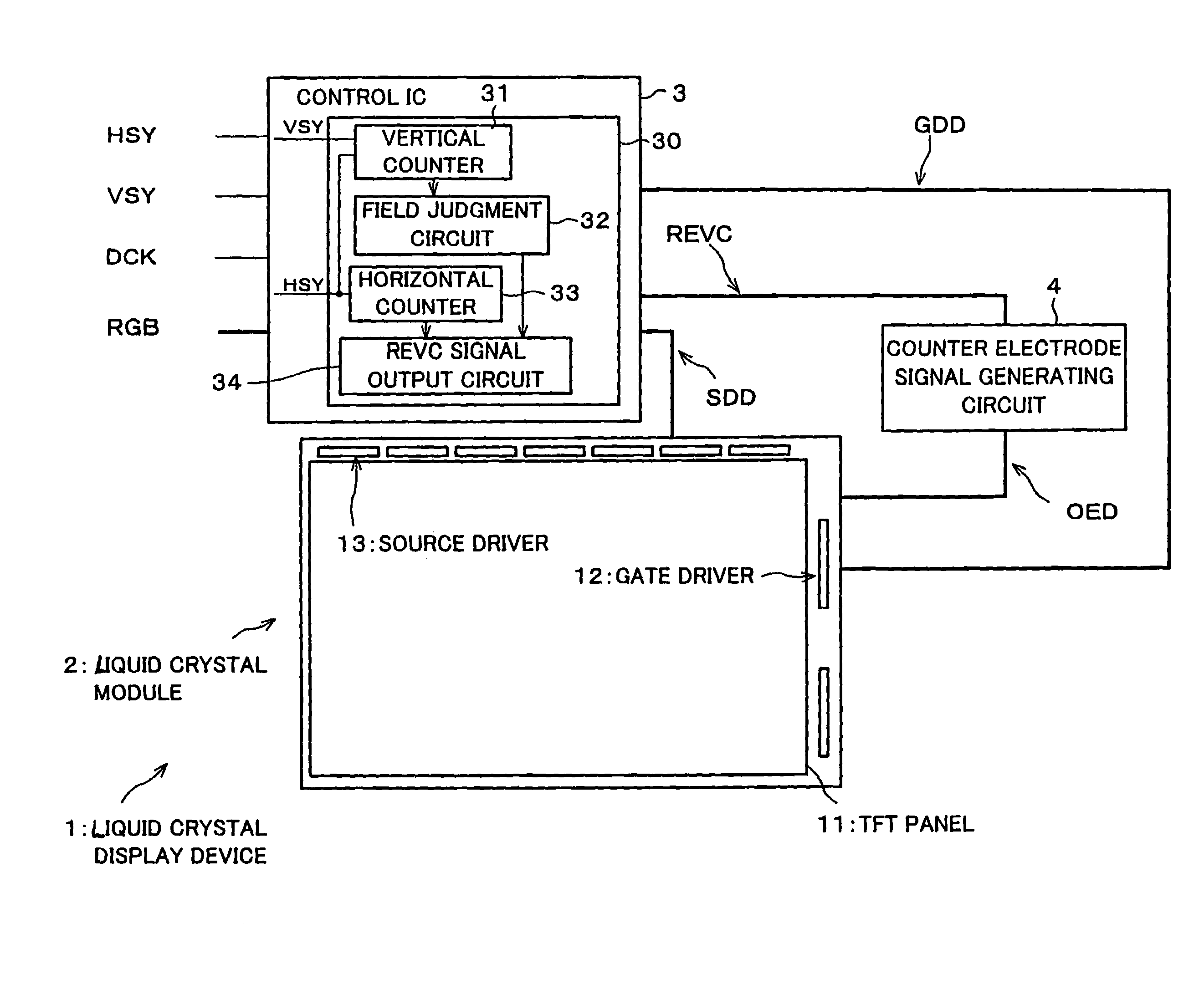
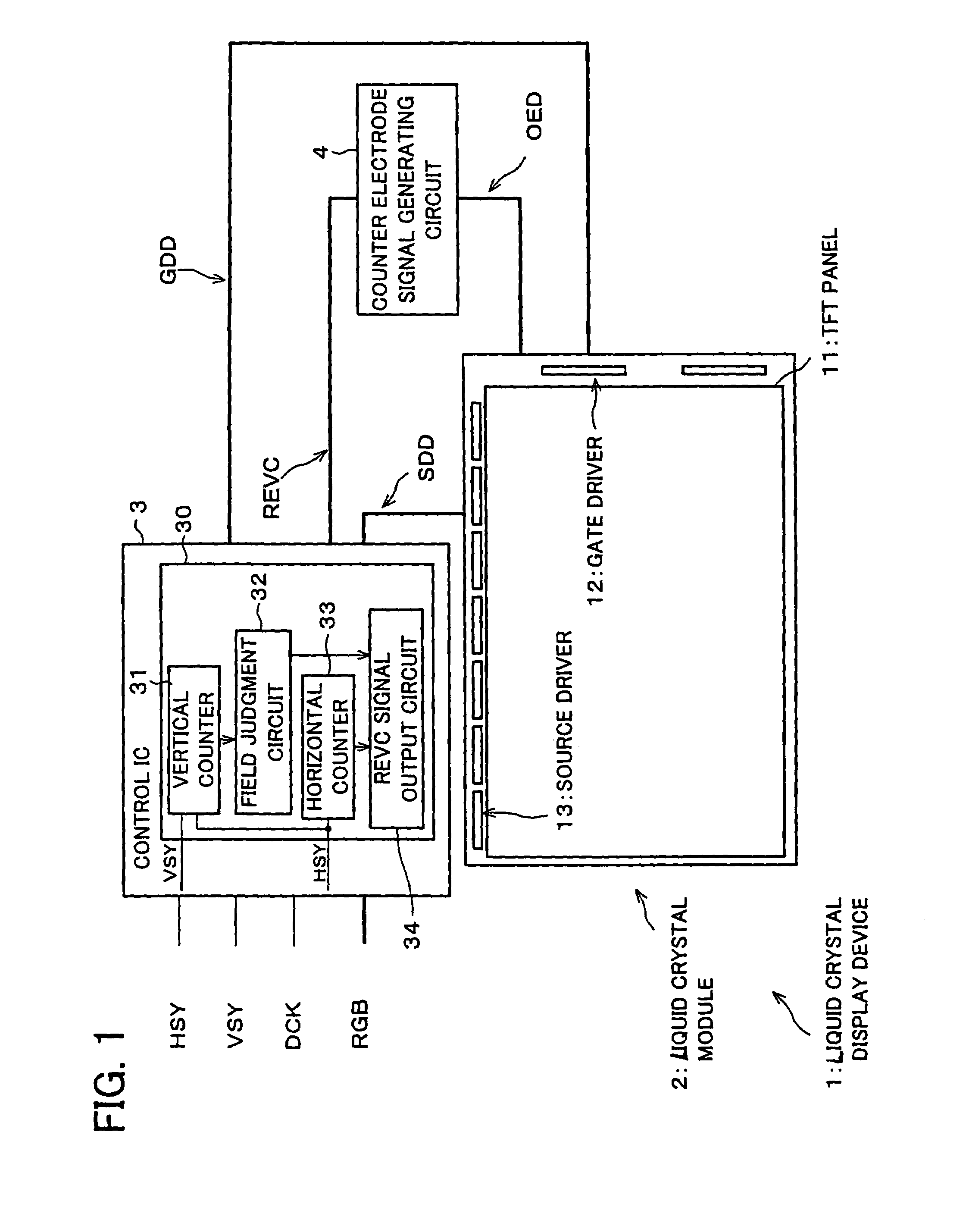
[0032]FIG. 1 is a block diagram schematically showing an arrangement of a liquid crystal display device 1 in accordance with the present embodiment. As shown in FIG. 1, the liquid crystal display device 1 is composed of a liquid crystal module 2 in which a gate driver 12 and a source driver 13 are provided on a TFT panel 11; and peripheral circuits including a control IC (integrated circuit) 3 and a counter electrode signal generating circuit 4.

[0033]The TFT panel 11 has an ordinary panel structure. Specifically, the TFT panel 11 is provided with a plurality of signal electrodes tha...


PUM

PropertyMeasurementUnit
frequencyaaaaaaaaaa
voltageaaaaaaaaaa
polarityaaaaaaaaaa

Abstract

A TFT panel includes (i) a plurality of signal electrodes, (ii) a plurality of scanning electrodes which cross the plurality of signal electrodes, (iii) an active element provided in a vicinity of each intersection at which one of the plurality of signal electrodes and one of the plurality of scanning electrodes cross and connected to the one of the plurality of signal electrodes and the one of the plurality of scanning electrodes, (iv) a pixel electrode driven by the active element, and (v) a counter electrode to which an AC signal is applied, and which faces the pixel electrode. The REVC signal generating circuit generates a counter electrode generating signal, which is to be generated into a counter electrode driving signal by a counter electrode signal generating circuit, in synchronism with a horizontal synchronizing signal in such a manner that the polarity is inverted every horizontal period, and, when one polarity has a length of periods longer than the other polarity during one vertical period, the both polarities of the counter electrode have the same root-mean-square value of voltage during one vertical period by inverting the polarity having the longer period at any timing. With this, it is possible to reduce a low-frequency sound caused by piezoelectricity of a liquid crystal capacitance.

Description

FIELD OF THE INVENTION[0001]The present invention relates to a driving method of a liquid crystal display device; and in particular to a liquid crystal display device capable of reducing a low-frequency sound caused by piezoelectricity of a liquid crystal capacitance and a driving method thereof.BACKGROUND OF THE INVENTION[0002]In a conventional liquid crystal display device that drives matrix electrodes using line inversion, a counter electrode driving signal is controlled to be inverted every horizontal period and every vertical period. Further, the counter electrode driving signal may be fixed at “Lo” during a retrace period in order to reduce differences in luminance among gate lines and to improve display quality; and the polarity of the counter electrode driving signal may be adjusted in order to prevent flicker and image burn on the panel, etc.[0003]Here, in the liquid crystal display device driven using line inversion, the counter electrode driving signal is inverted every h...

Claims


Application Information

Patent Timeline
Patent Type & Authority Patents(United States)
IPC IPC(8): G09G3/36G02F1/133G09G3/20G09G5/00
CPCG09G3/3614G09G3/3655G09G2320/02G09G5/006
Inventor RYUH, KENTAROH
Owner SHARP KK
Why Eureka
Try Eureka