Subsea actuator assemblies and methods for extending the water depth capabilities of subsea actuator assemblies

a technology of actuators and subsea, which is applied in the direction of fluid couplings, borehole/well accessories, vessel parts, etc., can solve the problems of special problems, special problems, and difficulties in the operation of such valves, and achieve the effects of improving the hydraulic pressure compensation system, increasing fluid pressure, and reducing siz

Inactive Publication Date: 2006-09-19
VETCO GRAY
View PDF12 Cites 60 Cited by
  • Summary
  • Abstract
  • Description
  • Claims
  • Application Information

AI Technical Summary

Benefits of technology

[0009]The invention provides an improved hydraulic pressure compensation system for valve actuator assemblies. The system of the present invention has particular application for subsea wellhead installations. The improved compensation system includes at least one valve actuator assembly having a housing that retains a reciprocable piston therewithin. The piston is spring biased into its fail safe configuration. The valve actuator assembly is hydraulically associated with an accumulator reservoir that defines a closed fluid reservoir and an open fluid reservoir that is exposed to ambient pressures. The two chambers are separated by a membrane. The valve actuator assembly is also operationally a

Problems solved by technology

Subsea environments create special problems for the operation of such valves.
However, difficulties arise when they are used at greater depths.
Special problems are created by placement of wellheads in deep waters.
The greater the water depth, the greater the spring force required to counteract the effects of hydrostatic head pressure on an unbalanced stem area.
Other constraints, particularly those relating to the size and weight

Method used


Image

  • Subsea actuator assemblies and methods for extending the water depth capabilities of subsea actuator assemblies
  • Subsea actuator assemblies and methods for extending the water depth capabilities of subsea actuator assemblies
  • Subsea actuator assemblies and methods for extending the water depth capabilities of subsea actuator assemblies

Examples


Embodiment Construction

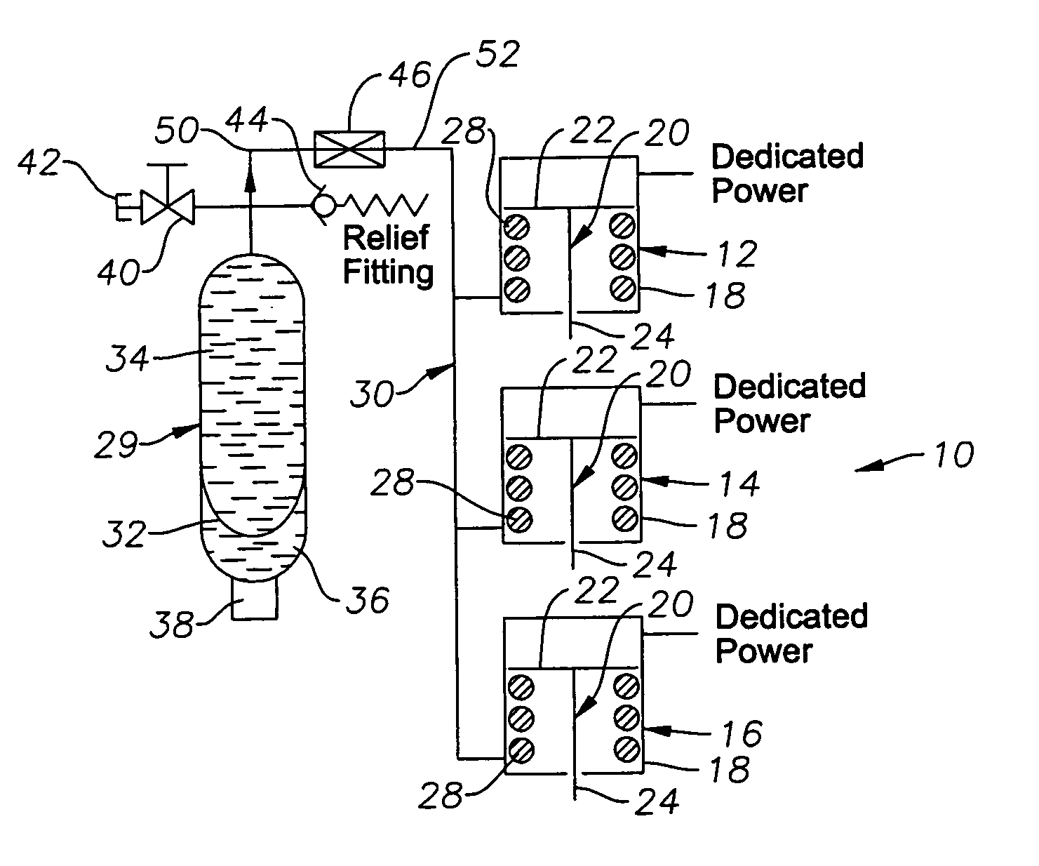
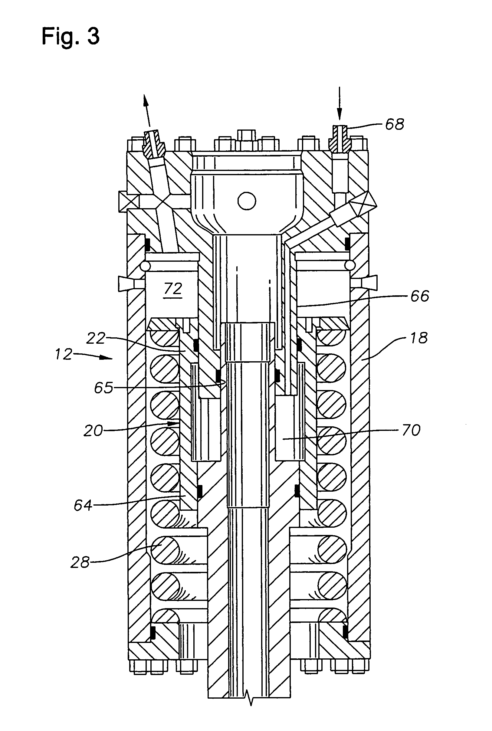
[0013]FIG. 1 depicts, in schematic fashion, an exemplary hydraulic pressure compensation system 10 for a plurality of subsea actuator assemblies 12, 14 and 16. The assemblies 12, 14 and 16 each include an outer, generally cylindrical housing 18 with a piston 20 that is moveably disposed therein. A single exemplary actuator assembly 12 is shown in side cross-section in FIG. 3. The piston 20 features a piston head 22 with a stem 24 that, when moved axially, actuates a valve (not shown). A compressible spring 28 is used to bias each of the pistons 20 into a “fail-safe” closed (or open) position within its housing 18. Although not shown in FIG. 1, an opposite end of stem 24 is exposed to sea water. This exposure creates a force equal to the hydrostatic pressure of the sea water times the pressure area of the stem. The force on stem 24 is opposite to the force exerted by spring 28. As FIG. 1 shows, dedicated hydraulic power is provided to each of the actuator assemblies 12, 14 and 16 and...


PUM


Abstract

A hydraulic pressure compensation system for valve actuator assemblies is described having particular application for subsea wellhead installations. The compensation system includes at least one valve actuator assembly having a housing that retains a reciprocable piston therewithin. The piston is spring biased into its fail safe configuration. The valve actuator assembly is hydraulically associated with an accumulator reservoir that defines a closed fluid reservoir and an open fluid reservoir that is exposed to ambient pressures. The two chambers are separated by a membrane. The valve actuator assembly is also operationally associated with a fluid pressure intensifier that boosts the ambient pressure of the accumulator so that an increased fluid pressure may be transmitted to the actuator assembly to bias the actuated valve toward its fail safe configuration. In a described embodiment, the fluid pressure intensifier comprises a housing that defines a chamber having a fluid inlet and fluid outlet. A dual-headed piston is moveably retained within the housing. The piston has an enlarged piston face and a reduced size piston face. Fluid pressure entering the fluid inlet is exerted upon the enlarged piston face, and due to the difference of piston face sizes, an increased pressure is transmitted out of the fluid outlet.

Description

CROSS-REFERENCE TO RELATED APPLICATIONS[0001]This application claims the priority of provisional patent application Ser. No. 60 / 314,725 filed Aug. 24, 2001.BACKGROUND OF THE INVENTION[0002]1. Field of the Invention[0003]The invention relates to actuator assemblies for the selective actuation of valves. In particular aspects, the invention relates to improved hydraulic pressure arrangements and fail safe systems for use in such assemblies.[0004]2. Description of the Related Art[0005]Gate valves and other sliding stem-type valves operate by selectively inserting a reciprocable stem into the flow of fluid to stop the flow when desired. Such valves assemblies are often used with subsea wellheads in order to control the flow of oil or gas from the wellhead. Conventional subsea actuator assemblies are used to selectively open and close valves in subsea Christmas trees, manifolds and other assemblies. Examples of such actuator assemblies are described in U.S. Pat. Nos. 4,311,297 and 4,650,...

Claims


Application Information

Patent Timeline
IPC IPC(8): F17D1/18F16K17/36E21B34/04
CPCE21B34/04E21B33/0355Y10T137/0396Y10T137/2036
Inventor ARMSTRONG, JOHN TAYLOR
Owner VETCO GRAY
Why Eureka
Try Eureka