Illuminator, image display comprising the same, liquid crystal television, liquid crystal monitor, and liquid crystal information terminal

a technology of image display and illumination, applied in the field of lighting systems, can solve the problems of large region occupied by the light source, difficulty in producing thin lcds, and the inability to increase the output of the light source without careful consideration, and achieve the effect of improving the brightness distribution of viewing angles

Inactive Publication Date: 2006-11-07
JAPAN DISPLAY CENTRAL CO LTD
View PDF13 Cites 9 Cited by
  • Summary
  • Abstract
  • Description
  • Claims
  • Application Information

AI Technical Summary

Benefits of technology

[0010]The invention is directed to solving the foregoing problems and a first object of the invention is therefore to provide an image display apparatus, liquid crystal television, liquid crystal monitor and liquid crystal data terminal unit which are capable of providing an improved brightness distribution for viewing angles.

Problems solved by technology

If more cold cathode tubes are used, the volume of the cold cathode tubes increases with the result that the region occupied by the light source becomes larger.
If a cold cathode tube having increased output is employed, difficulties are encountered in producing thin LCDs because the size of a cold cathode tube increases as its output increases.
Further, there are restrictions on electric power consumption, and therefore the output of the light source cannot be increased without careful consideration.
In this case, there is the problem that when the viewer's eyes move from the center toward an edge of the screen of the LCD, the brightness increases with its peak in a certain region so that images appear awkward.

Method used


Image

  • Illuminator, image display comprising the same, liquid crystal television, liquid crystal monitor, and liquid crystal information terminal
  • Illuminator, image display comprising the same, liquid crystal television, liquid crystal monitor, and liquid crystal information terminal
  • Illuminator, image display comprising the same, liquid crystal television, liquid crystal monitor, and liquid crystal information terminal

Examples


example 1

[0097]Example 1 of the invention is associated with a backlight. The backlight of Example 1 will be explained by comparison with a comparative example.

[0098]In both Example 1 and the comparative example, a rectangular optical waveguide having 7-inch long diagonal lines and a thickness of about 10 mm was used as the optical waveguide 103, and cold cathode tubes having an output of about 100 W were used as the arc tubes 101.

[0099]In the comparative example, the end faces of the optical waveguide 103 for light entrance (hereinafter referred to as “light entrance end faces”) are perpendicular to the main faces like the prior art. When the brightness of light going out of the upper face of the optical waveguide was measured, it was found to be about 4,500 to 5,000 candela.

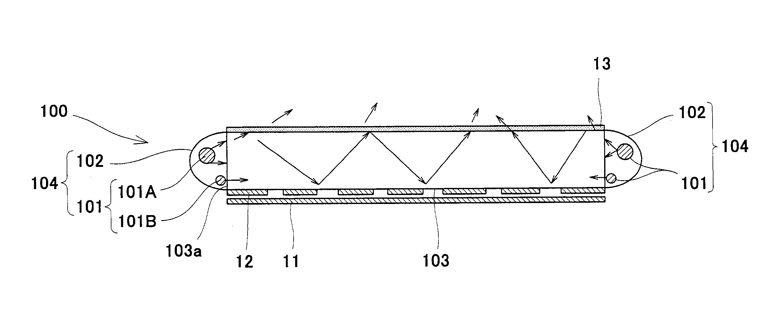
[0100]Then, the light entrance end faces 103a of the optical waveguide 103 were cut at 45 degrees to the main faces, thereby preparing the optical waveguide 103 of Example 1. Further, the reflectors 102 each having a li...

example 2

[0114]Example 2 of the invention is associated with a backlight. The backlight of Example 2 will be described by comparison with a comparative example. In both Example 2 and the comparative example, an optical waveguide having the same size as that of Example 1 of the first embodiment was used. In the comparative example, two cold cathode tubes having a diameter of 2.5 mm and an output power of 100 W were aligned 5 mm away from a light entrance end face of the optical waveguide so as to be parallel with the light entrance end face. By measurement, the brightness of the light going out of the optical waveguide through its upper face was found to be 8,000 to 9,000 candela.

[0115]In Example 2, a cold cathode tube 101B having a diameter of 1.5 mm and an output power of 60 W and a cold cathode tube 101A having a diameter of 2.5 mm and an output power of 100 W were used as the light emitter 101, as shown in FIG. 3. The cold cathode tube 101B of a diameter of 1.5 mm was placed just in front...

example 3

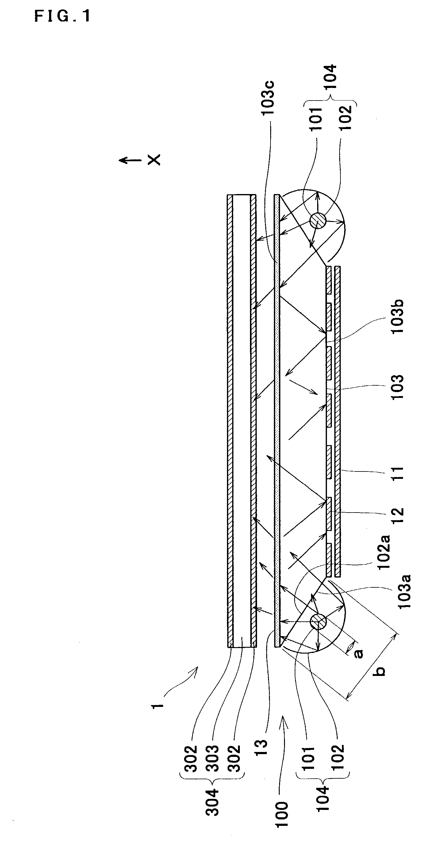
[0125]Example 3 of the invention is associated with a LCD. The LCD element of Example 3 will be explained by comparison with a comparative example. In both Example 3 and the comparative example, the OCB liquid crystal mode, which provided high response speed, was used as the liquid crystal cell 303 for the liquid crystal element 304. In the comparative example, the backlight prepared in Example 2 of the second embodiment was used as the backlight 100 without modification. Specifically, the diffusion sheet 13 was disposed on the upper face 103c of the optical waveguide 103. On the other hand, in Example 3, a backlight, which was similar to that of Example 2 of the second embodiment except that the scattering anisotropic film 301 was disposed on the upper face 103c of the optical waveguide 103 in place of the diffusion sheet 13, was used. Accordingly, the size of the optical waveguide 103 was 7 inches in both Example 3 and the comparative example.

[0126]The result of a comparison betwe...


PUM

PropertyMeasurementUnit
thicknessaaaaaaaaaa
diameteraaaaaaaaaa
output poweraaaaaaaaaa

Abstract

The invention provides an image display apparatus (1) comprising a lighting system (100); a LCD element (304); and an actuating means for varying the transmittance of the LCD element (304) according to image signals, wherein the LCD element (304) is designed such that when the angle of view with respect to a specified direction of a screen varies provided that the entire LCD element (304) is in a white display mode, transmittance varies such that it has peak values at viewing angles other than viewing angles in the vicinity of 0 degree, and wherein the lighting system (100) is designed such that the intensities of light beams emitted in the directions of the viewing angles in the vicinity of 0 degree are higher than the intensities of light beams emitted in the directions of the viewing angles at which the transmittance has a peak value.

Description

TECHNICAL FIELD[0001]The present invention relates to a lighting system, as well as an image display apparatus, liquid crystal television, liquid crystal monitor and liquid crystal data terminal unit using the same.BACKGROUND ART[0002]A liquid crystal display (LCD), which is one example of image display apparatuses, is comprised of a LCD element; a backlight positioned under the LCD element, for feeding light to the LCD element; and a circuit board or the like for actuating the LCD element. In the LCD element, an electrode, alignment layer etc. formed from, for example, a transparent conductive thin film are laminated on two transparent glass substrates; the glass substrates are opposed with a specified spacing between such that their laminated surfaces face each other; a liquid crystal is confined between the two glass substrates; and a polarizing plate is disposed outside both glass substrates.[0003]FIG. 10 shows a conventional backlight of the edge light type. The backlight 500 c...

Claims


Application Information

Patent Timeline
Patent Type & Authority Patents(United States)
IPC IPC(8): G09G3/36F21V8/00G02B6/00G02F1/13357
CPCG02B6/0031G02B6/0051G02F1/133615G02B6/0036G02B6/0043G02B6/0071
Inventor OGIWARA, AKIFUMIKURATOMI, YASUNORIASAYAMA, JUNKOKOMORI, KAZUNORI
Owner JAPAN DISPLAY CENTRAL CO LTD
Why Eureka
Try Eureka