Liquid crystal display device using external electrode fluorescent lamps

a technology of fluorescent lamps and liquid crystal displays, which is applied in the direction of lighting devices, lighting and heating apparatus, instruments, etc., can solve the problems of difficult to satisfy a narrow picture frame, and achieve the effect of improving the brightness of the external electrode region, and favorable brightness distribution over the whole surfa

Inactive Publication Date: 2011-06-28
PANASONIC LIQUID CRYSTAL DISPLAY CO LTD +1
View PDF6 Cites 2 Cited by
  • Summary
  • Abstract
  • Description
  • Claims
  • Application Information

AI Technical Summary

Benefits of technology

[0011]An external electrode of the external electrode fluorescent lamp is characterized in that the longer a lamp length of the external electrode fluorescent lamp, a length of a forming region in the lamp axial direction is increased. To match a light emitting region of the external electrode fluorescent lamp with a display region of the liquid crystal display panel, a width of an outer periphery (picture frame) which the region of the external electrode occupies is increased and hence, the brightness in regions at both ends of the external electrode fluorescent lamp is lowered. The larger a size of the liquid crystal display device, this phenomenon becomes more conspicuous. This implies that it is difficult to satisfy a demand for narrow picture frame in recent years. To satisfy the demand for the narrow picture frame, it is necessary to arrange a portion of the external electrode of the external electrode fluorescent lamp within a display region inside a picture frame region. In this case, an external electrode region within the display region constitutes a non-light-emitting region thus lowering the brightness.
[0012]Accordingly, it is an object of the present invention to provide a liquid crystal display device which can, when an external electrode portion of an external electrode fluorescent lamp is arranged within a display region of a liquid crystal display panel, realize the narrowing of a picture frame by effectively reducing the generation of brightness irregularities attributed to lowering of the brightness of the external electrode region.
[0017]The above-mentioned eaves and inclined portions formed on the upper side frame have a function of improving the brightness of an external electrode region and can realize the liquid crystal display device which exhibits the favorable brightness distribution over the whole surface of a display region without requiring a wide picture frame of the liquid crystal display panel. Here, the eaves can also have, in addition to the function of improving the brightness of the external electrode region, a function of preventing an electric shock due to a high voltage applied to the external electrode.

Problems solved by technology

This implies that it is difficult to satisfy a demand for narrow picture frame in recent years.

Method used


Image

  • Liquid crystal display device using external electrode fluorescent lamps
  • Liquid crystal display device using external electrode fluorescent lamps
  • Liquid crystal display device using external electrode fluorescent lamps

Examples


embodiment 1

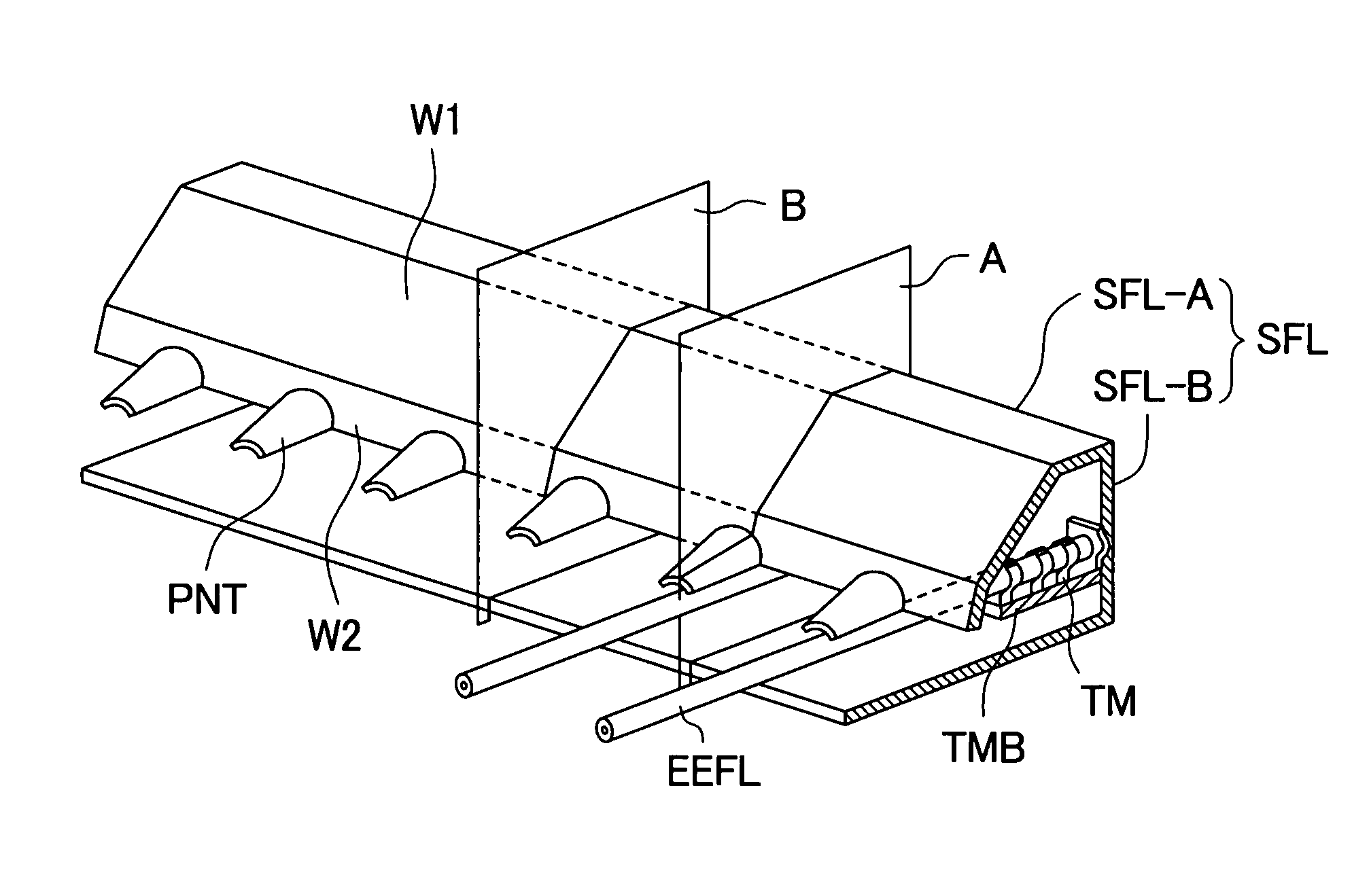
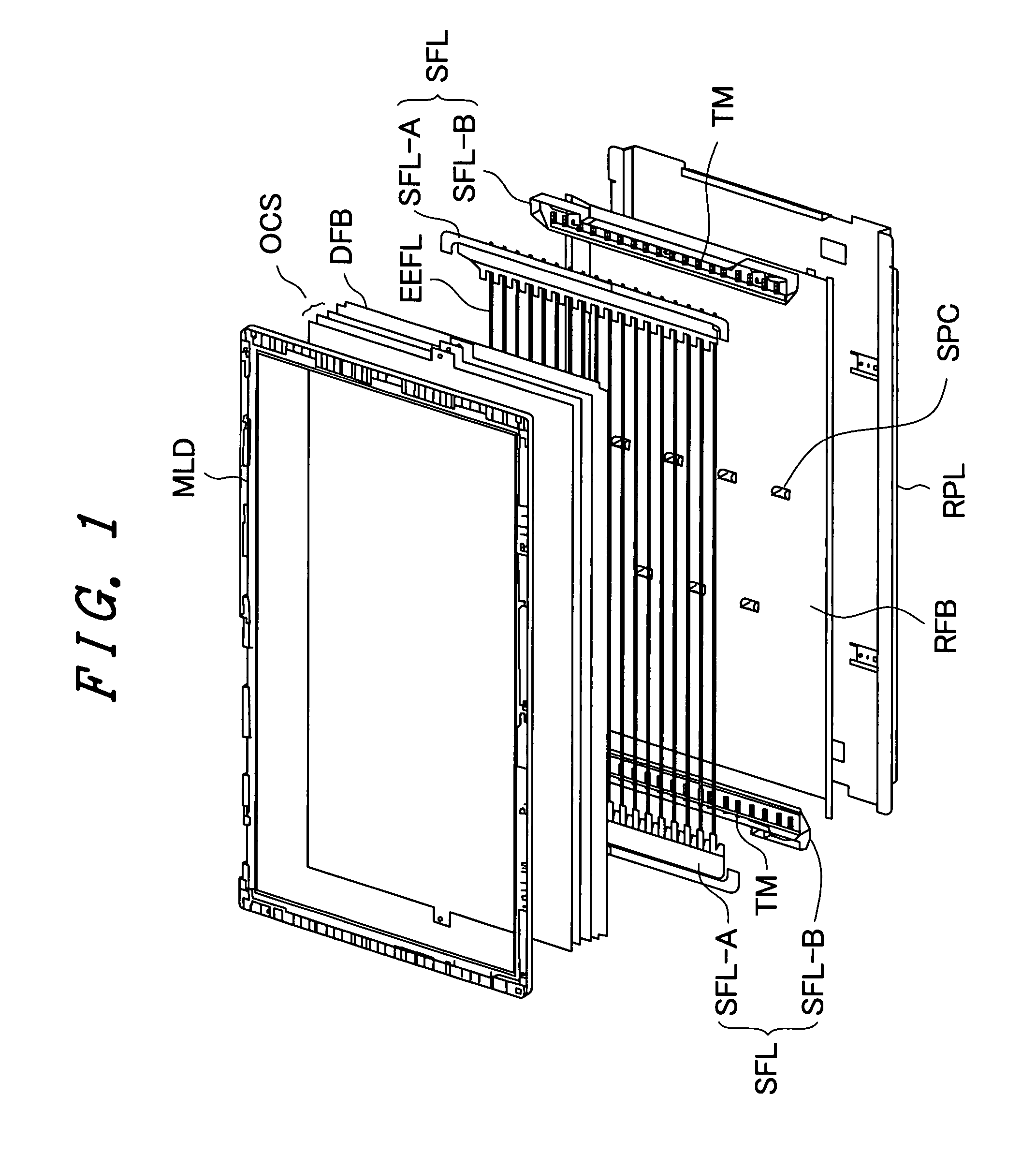
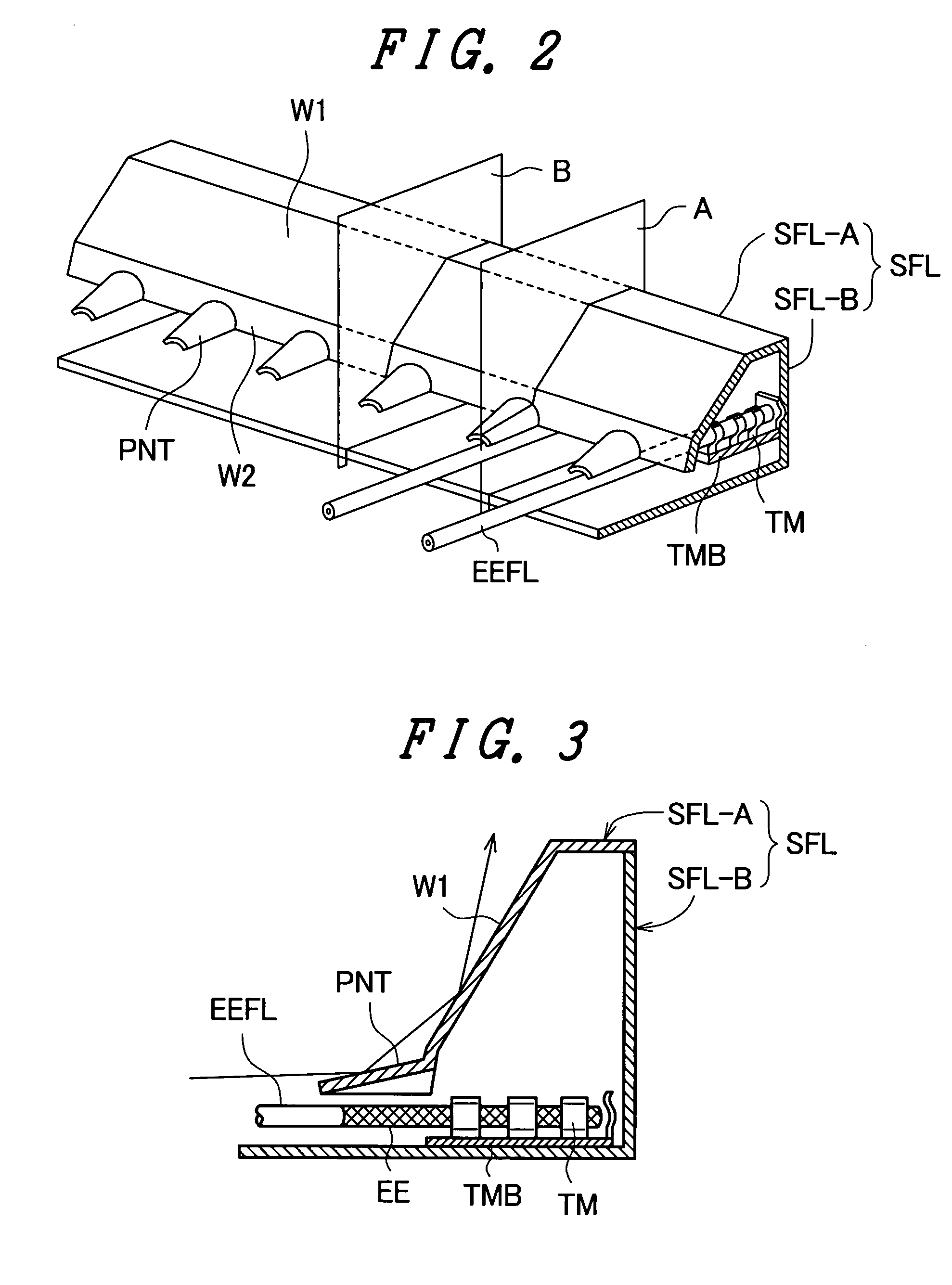
[0030]FIG. 1 is a developed perspective view for explaining an embodiment of a backlight structural body used in a liquid crystal display device according to the present invention. The backlight structural body is of a direct-light type. The backlight structural body of this embodiment is configured such that between a back plate RPL and a mold frame MLD, a reflector RFB, side frames SFL, a diffusion plate DFB and an optical compensation sheet group OCS which is formed by stacking a prism sheet and a diffusion sheet are arranged. Here, each side frame SFL is constituted of a lower side frame SFL-B which includes electricity supply terminals TM which fixedly holds both ends of a plurality of external electrode fluorescent lamps EEFL constituting linear light sources and supply electricity, and an upper side frame SFL-A which includes eaves covering external electrode portions of the external electrode fluorescent lamps EEFL.

[0031]Here, in the backlight structural body having such a c...

embodiment 2

[0040]FIG. 5 is a perspective view of an essential part of an upper side frame for explaining an embodiment 2 of the liquid crystal display device of the present invention. Symbols which are equal to the symbols used in the explanatory views of the above-mentioned embodiment indicate identical functional parts. The embodiment 2 is characterized in that the above-mentioned eaves PNT are formed of rectangular flat plates which project from the upper side frame SFL-A in the longitudinal direction of the external electrode fluorescent lamps EEFL and are arranged parallel to an arrangement plane of the plurality of external electrode fluorescent lamps EEFL. The rectangular eaves PNT project in parallel to the external electrode fluorescent lamps EEFL from the lower end of the wall surface W2 of the upper side frame SFL-A for covering external electrodes EE. However, the eaves PNT may be inclined to gradually approach the external electrode fluorescent lamps EEFL from the lower end of the...

embodiment 3

[0042]FIG. 6 is a perspective view of an essential part of an upper side frame for explaining an embodiment 3 of the liquid crystal display device of the present invention. Symbols which are equal to the symbols used in the explanatory views of the above-mentioned embodiment indicate identical functional parts. The embodiment 3 is characterized in that the above-mentioned eaves PNT are formed into a shape which includes an upper surface which projects in the longitudinal direction of external electrode fluorescent lamps EEFL from an upper side frame SFL-A and covers external electrodes EE of the plurality of external electrode fluorescent lamps EEFL from above and side surfaces which cover the external electrodes EE together with the upper surface.

[0043]The eaves PNT having such a shape project from the lower end of the wall surface W2 of the upper side frame SFL-A in parallel to the external electrode fluorescent lamps EEFL and cover the external electrodes EE. However, a bottom su...


PUM

PropertyMeasurementUnit
diameteraaaaaaaaaa
shapeaaaaaaaaaa
inclination angleaaaaaaaaaa

Abstract

A backlight structural body of a liquid crystal display device includes, between a back plate and a frame-like mold frame, a plurality of external electrode fluorescent lamps which is arranged in parallel to each other and a pair of side frames which includes electricity supply terminals which electrically connect electrode portions of the plurality of external electrode fluorescent lamps in parallel to each other. The side frame is constituted of a lower side frame which fixes the electricity supply terminals and an upper side frame which is assembled to the lower side frame while covering the electrode portions of the external electrode fluorescent lamps which are connected to the electricity supply terminals. The upper side frame includes eaves which project in the longitudinal direction of the external electrode fluorescent lamps in a state that the eaves individually cover the respective electrode portions of the external electrode fluorescent lamps.

Description

[0001]The present application claims priority from Japanese applications JP2006-238544 filed on Sep. 4, 2006, the content of which is hereby incorporated by reference into this application.BACKGROUND OF THE INVENTION[0002]1. Field of the Invention[0003]The present invention relates to a liquid crystal display device, and more particularly to a backlight structural body which uses an external electrode fluorescent lamp (EEFL).[0004]2. Description of the Related Art[0005]A liquid crystal display device has been widely spreading as a display device of a television receiver set or an information terminal. Usually, in the liquid crystal display device of this type which is relatively large in size and has a screen which is required to exhibit high brightness, as a backlight structural body which constitutes an auxiliary illumination device of the liquid crystal display device, there is adopted a so-called direct-light-type backlight structural body which arranges a plurality of linear li...

Claims


Application Information

Patent Timeline
Patent Type & Authority Patents(United States)
IPC IPC(8): G02F1/1335G02F1/1333
CPCG02F1/133608G02F1/133604
Inventor ITO, YOICHISUMIYA, NAOTOSHI
Owner PANASONIC LIQUID CRYSTAL DISPLAY CO LTD
Why Eureka
Try Eureka