Reference image display method for ultrasonography and ultrasonograph

a display method and ultrasonography technology, applied in the field of reference image display methods for ultrasonography and ultrasonic diagnosis apparatuses, can solve the problems of not giving consideration to a scheme for matching display regions and the magnifications of reference, and the difficulty of recognizing the association relationship of portions he or she desires to observe, so as to achieve the effect of free-setting reference points and improving comparison and observation accuracy

Active Publication Date: 2007-01-11
FUJIFILM HEALTHCARE CORP
View PDF30 Cites 113 Cited by
  • Summary
  • Abstract
  • Description
  • Claims
  • Application Information

AI Technical Summary

Benefits of technology

[0021] Further, in addition to the above-described configuration, the ultrasonic diagnosis apparatus can include: a position sensor for detecting a position and an inclination of the ultrasonic probe in association with a reference coordinate system; scan-plane-coordinate determining means for determining scan-plane coordinates of an ultrasonic image captured by the ultrasonic probe in association with the reference coordinate system, in accordance with an output from the position sensor; reference-point inputting means for setting a reference point on a reference image displayed on the screen based on the volume image data obtained in association with the reference coordinate system; volume-data-coordinate determining means for determining coordinates of tomographic data of the volume image data associated with the scan-plane coordinates, by determining a coordinate relationship between the position of the ultrasonic probe and a region that corresponds to the reference point and that exists on an ultrasonic image obtained by bringing the ultrasonic probe in contact with a body surface of the patient; and volume-data-coordinate storing means for storing the tomographic-image-data coordinates determined by the volume-data-coordinate determining means. The reference-image reconstructing means can read the coordinates of the tomographic image data, associated with the scan-plane coordinates determined by the scan-plane-coordinate determining means, from the volume-data-coordinate storing means and can extract the reference image. With this arrangement, the reference point for aligning the coordinate systems can be set inside the body of the patient. Thus, compared to the prior art in which a reference point is set on the body surface, the freedom of setting the reference point is increased and thus the accuracy of comparison and observation can be further improved.

Problems solved by technology

However, in the prior art, although a reference image of a cross section corresponding to the scan plane of an ultrasonic image is cut out and is displayed on the same screen, no consideration is given to a scheme for matching display regions and the magnifications of a reference image and an ultrasonic image and.
Thus, when the reference image and the ultrasonic image are merely displayed in an aligned manner, there is also a problem in that it is difficult to recognize an association relationship of portions he or she desires to observe.
However, in the prior art, there is a problem in that no consideration is given to a scheme for facilitating the recognition of the positional relationship between the current ultrasonic scan plane and the target.

Method used


Image

  • Reference image display method for ultrasonography and ultrasonograph
  • Reference image display method for ultrasonography and ultrasonograph
  • Reference image display method for ultrasonography and ultrasonograph

Examples


first embodiment

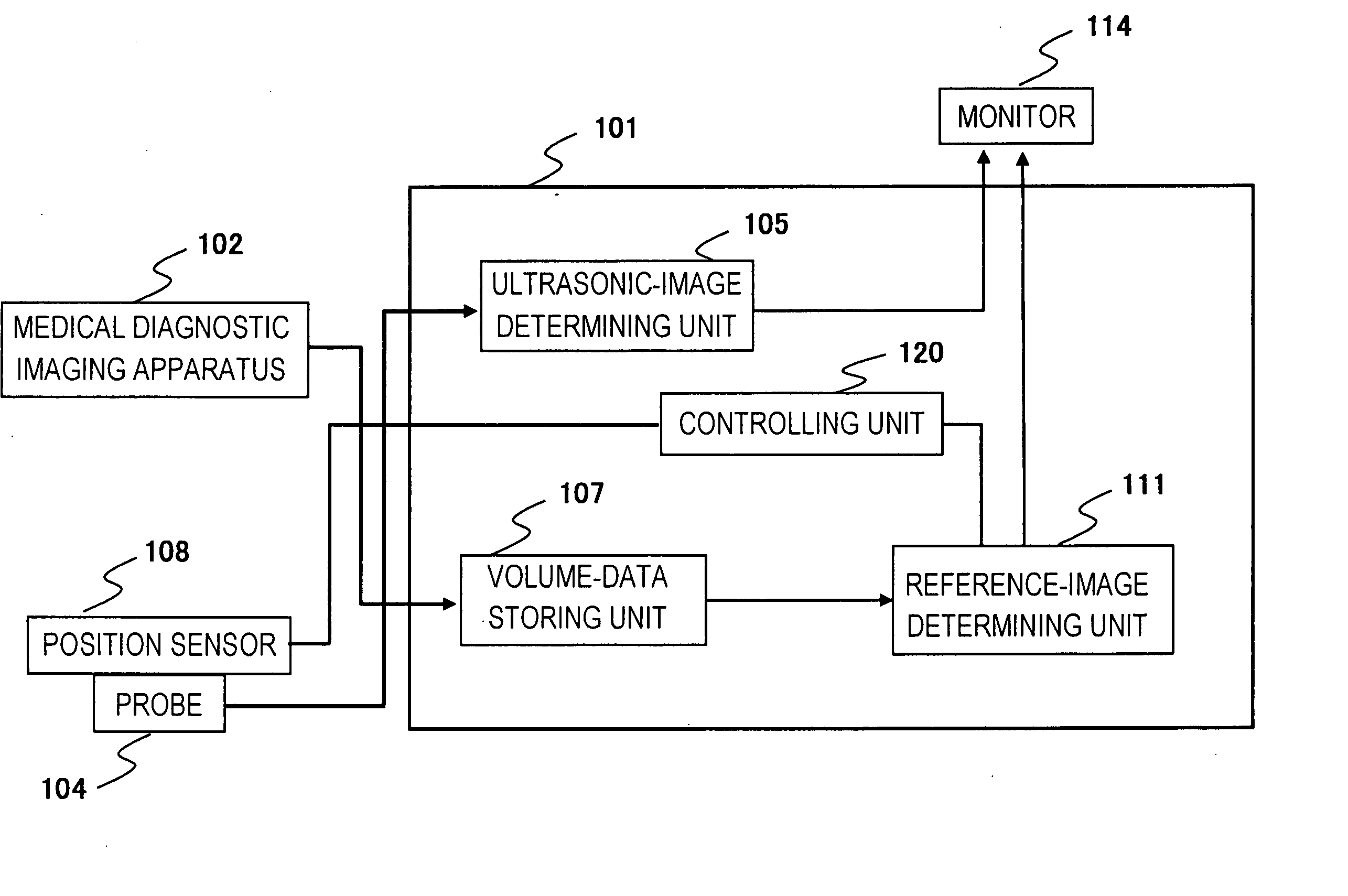
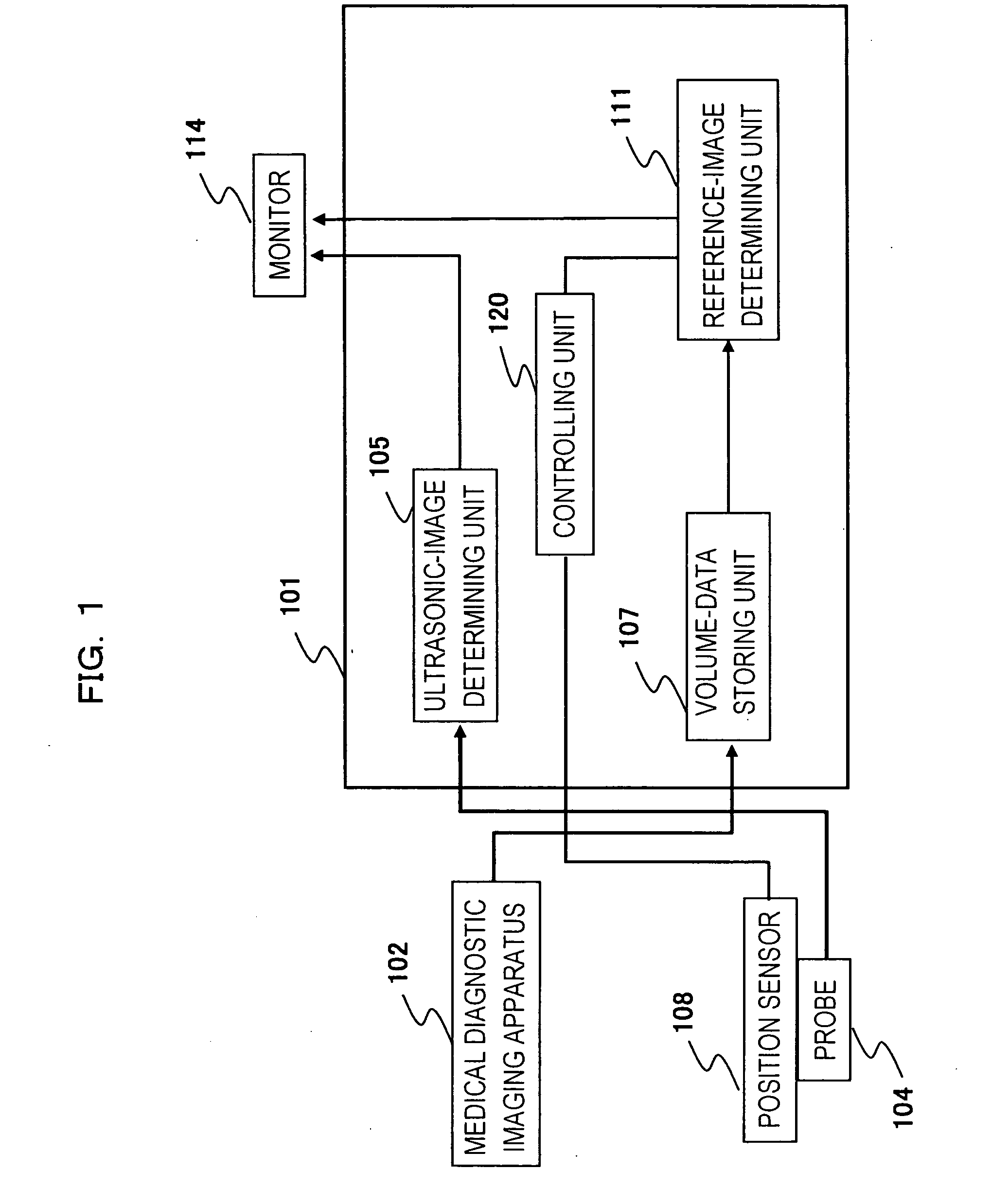
[0038]FIG. 1 is block diagram of a basic diagnostic imaging system to which an ultrasonic diagnosis apparatus of one embodiment of the present invention is applied. As shown, the diagnostic imaging system includes an ultrasonic diagnosis apparatus 101 according to one embodiment of the present invention and a medical diagnostic imaging apparatus 102 for obtaining volume image data that provides as a reference image. The volume image data refers to the data of multi-slice images obtained by capturing the inside of the body of a patient along multiple slice planes. The data of the volume images captured by the medical diagnostic imaging apparatus 102 is input to the ultrasonic diagnosis apparatus 101. A computed tomography apparatus (X-ray CT apparatus) or a magnetic resonance imaging apparatus (MRI apparatus) can be used as the medical diagnostic imaging apparatus 102. CT images and MR images have higher image qualities than ultrasonic images, as is known, and thus are suitable as re...

second embodiment

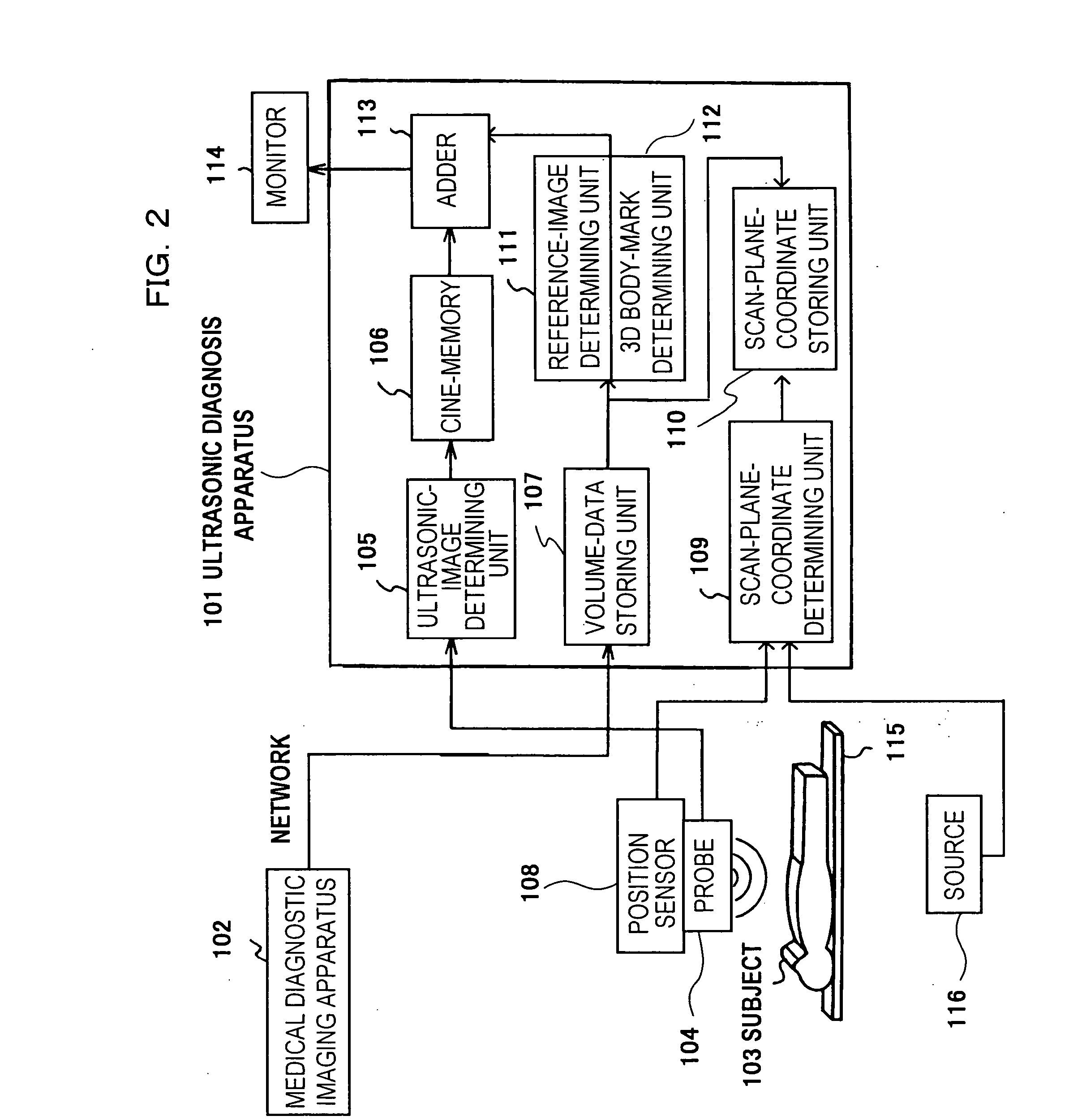
[0043]FIG. 2 shows the configuration of a specific diagnostic imaging system to which an ultrasonic diagnosis apparatus of the present invention is applied. In the figure, means having the same functional configurations as those in FIG. 1 are denoted with the same reference numerals and the descriptions thereof are omitted. In FIG. 2, a scan-plane-coordinate determining unit 109 and a scan-plane-coordinate storing unit 110 correspond to the configuration of the major unit of the controlling unit 120. A cine-memory 106 stores an ultrasonic image reconstructed by the ultrasonic-image determining unit 105. A 3D body-mark determining unit 112 is provided in connection with the reference-image determining unit 111. An adder 113 is configured as image processing means for appropriately combining images generated by the cine-memory 106, the reference-image determining unit 111, and the 3D body-mark determining unit 112. The monitor 114 is adapted to display images generated by the cine-mem...

third embodiment

[0061]FIG. 6 shows the configuration of a diagnostic imaging system to which an ultrasonic diagnosis apparatus of another embodiment of the present invention is applied. In FIG. 6, what are different from the embodiment shown in FIG. 2 are that a breathing sensor 117 for detecting the amount of breathing of the patient 103 and a posture sensor 118 for detecting the body movement are provided and outputs of the detections are input to the scan-plane-coordinate determining unit 109. Although processing for associating a volume-image-data coordinate system with a scan-plane coordinate system was omitted in the embodiment in FIG. 2, details thereof will be described.

[0062] In the present embodiment, as shown in FIG. 7A, the position sensor 108 is attached to one surface of the probe 104 to make it possible to detect the position and inclination of the probe 104, i.e., the position and inclination of the ultrasonic scan plane, in a coordinate system formed by the source 116. In FIG. 7A,...


PUM


Abstract

An ultrasonic image 105, 106 is captured by an ultrasonic probe 104. A reference image 111 is obtained by extracting a tomographic image corresponding to the scan plane of the ultrasonic image from volume image data that is pre-obtained by a diagnostic imaging apparatus 102 and that is stored in a volume-data storing unit 107. The ultrasonic image and the reference image 111 are displayed on the same screen 114. In this case, of the reference image, a portion corresponding to the view area of the ultrasonic image is extracted and the resulting reference image having the same region as the ultrasonic image is displayed as a fan-shaped image.

Description

TECHNICAL FIELD [0001] The present invention relates to reference-image display methods for ultrasonography and ultrasonic diagnosis apparatuses using the methods. More specifically, the present invention relates to a technology preferably used for reconstructing, using multi-slice-image data of a patient obtained by a diagnostic imaging apparatus, a reference image of the same cross section as an ultrasonic scan plane in real time and for displaying the reference image and an ultrasonic image on the same screen. Examples of the diagnostic imaging apparatus include an ultrasonic diagnosis apparatus, a magnetic resonance imaging (MRI) apparatus, and an X-ray computed tomography (X-ray CT) apparatus. BACKGROUND ART [0002] Ultrasonic diagnosis apparatuses, which are one type of diagnostic imaging apparatuses, are frequently used for diagnosis, since they are easy to handle and are capable of performing noninvasive observation of arbitrary cross sections in real time. On the other hand,...

Claims


Application Information

Patent Timeline
Patent Type & Authority Applications(United States)
IPC IPC(8): A61B8/00A61B8/13G06T7/00
CPCA61B8/13A61B8/463A61B8/466G06T7/0028G06T7/0038G06T19/00A61B8/483G06T2207/10088G06T2207/10132G06T2207/30101G06T2219/028Y10S128/916G06T2207/10081G06T7/33G06T7/38
Inventor ARAI, OSAMU
Owner FUJIFILM HEALTHCARE CORP
Why Eureka
Try Eureka