vehicle fuel supply

A fuel supply device and fuel supply technology are applied in the directions of liquid fuel feeders, charging systems, bicycle accessories, etc., which can solve problems such as assembly difficulties, and achieve the effects of improving assembly performance and suppressing external interference.

Active Publication Date: 2011-12-21
HONDA MOTOR CO LTD
View PDF8 Cites 3 Cited by
  • Summary
  • Abstract
  • Description
  • Claims
  • Application Information

AI Technical Summary

Problems solved by technology

[0004] However, in the above-mentioned conventional structure, the secondary filter covered by the casing is installed along the center frame of the motorcycle through the brack

Method used


Image

  • vehicle fuel supply
  • vehicle fuel supply
  • vehicle fuel supply

Examples


Example Embodiment

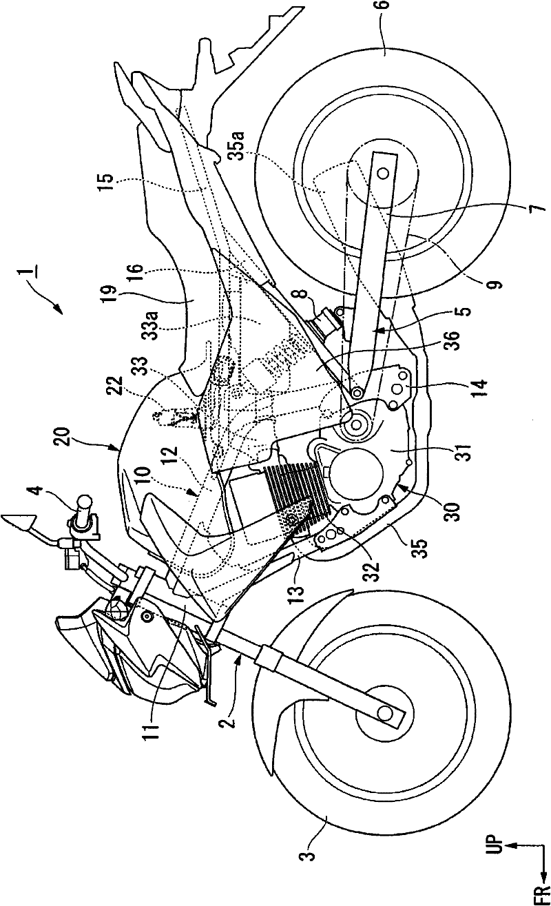
[0050] Hereinafter, embodiments of the present invention will be described with reference to the drawings. In addition, the orientation of the front, back, left, and right in the following description is the same as the orientation of the vehicle described below unless otherwise specified. In addition, in appropriate positions in the drawings used in the following description, an arrow FR indicating the front of the vehicle, an arrow LH indicating the left side of the vehicle, and an arrow UP indicating the upper side of the vehicle are shown.

[0051] in figure 1 In the two-wheeled motorcycle (straddle-type vehicle) 1 shown, the body frame 10 is integrally joined by welding various steel materials, and the body frame 10 has a front wheel suspension system capable of steering 2 of the head tube 11; the main frame 12 that extends backward from the head tube 11 and then buckles and extends diagonally downward backward; the down tube 13 that extends diagonally downward from the head...


PUM


Abstract

The present invention provides a fuel supply apparatus, wherein relative to a fuel pump inside a fuel box, a fuel filter is arranged outside the fuel box, thereby increasing the assembling property of the fuel box on vehicle body. A fuel pump (22) is configured inside the fuel box from the bottom (24) of the fuel box (20), and the fuel filter (41) is arranged at the bottom (22b) of the fuel pump (22).the rear lower end of a carrying bracket (51) carrying the fuel filter (41) is located lower than the fuel filter (41).

Description

technical field [0001] The present invention relates to a fuel supply device suitable for saddled vehicles such as motorcycles. Background technique [0002] In the past, in the above-mentioned fuel supply device, if relying on fuel with fine particles such as ethanol gasoline (ethanol), in order to lengthen the replacement cycle of the fuel filter, there is a finer filter on the downstream side of the coarse primary filter. In the case of a secondary filter (for example, refer to Patent Document 1.). In this aspect, the secondary filter (143) arranged on the downstream side of the fuel passage compared to the fuel pump (92) is set so that the mesh ratio is arranged on the upstream side of the fuel passage compared to the fuel pump (92). The primary filter (141) is thin, and the secondary filter is covered with a housing (143A) and installed along the center frame (23) of the motorcycle via a bracket (146). [0003] Patent Document 1: Japanese Patent Laid-Open No. 2008-248...

Claims


Application Information

Patent Timeline
IPC IPC(8): B62J37/00F02M37/22
CPCY02T10/32
Inventor 西山弘忠
Owner HONDA MOTOR CO LTD
Why Eureka
Try Eureka