Eureka AIR delivers breakthrough ideas for toughest innovation challenges, trusted by R&D personnel around the world.

Hydraulic shock absorber

Inactive Publication Date: 2008-01-31
SHOWA CORP
View PDF17 Cites 3 Cited by
  • Summary
  • Abstract
  • Description
  • Claims
  • Application Information

AI Technical Summary

Benefits of technology

[0008]An object of the present invention is to improve an assembling characteristic while reducing rotational friction which a spring bearing applies to a suspension spring, in a hydraulic shock absorber in which the suspension spring is interposed between a lower spring bearing in a bottom portion side of an inner tube and an upper spring bearing m a piston support member side.
[0009]The present invention relates to a hydraulic shock absorber. An inner tube in an axle side is slidably inserted into an outer tube in a vehicle body side. A partition wall member is provided in an inner periphery of the inner tube. A working fluid chamber is comparted on a lower side of the partition wall member. An oil reservoir chamber is comparted on an upper side of the partition wall member. A piston support member attached to the outer tube side is inserted into the working fluid chamber through the partition wall member. A piston sliding within the working fluid chamber is provided in a leading end portion of the piston support member. A suspension spring is interposed between an upper spring bearing in the piston support member side and a lower spring bearing in a bottom portion side of the inner tube, within the working fluid chamber of the inner tube. The upper spring bearing is attached to the leading end portion of the piston support member with the leading end portion being closer to the suspension spring than the piston in such a manner as to be rotatable and to be prevented from falling away.

Problems solved by technology

In the hydraulic shock absorber described in the patent document 1, when the suspension spring repeats extension and contraction while accompanying a torsion between the upper and lower spring bearings, the suspension spring receives a rotational friction resistance force from the upper and lower spring bearings, and it is difficult to smoothly execute the extension and contraction of the suspension spring.
It is difficult to accurately seat the upper spring bearing and the friction resistance force reducing means on the suspension spring in accordance with correct assembling order and posture.

Method used


Image

  • Hydraulic shock absorber
  • Hydraulic shock absorber
  • Hydraulic shock absorber

Examples


Embodiment Construction

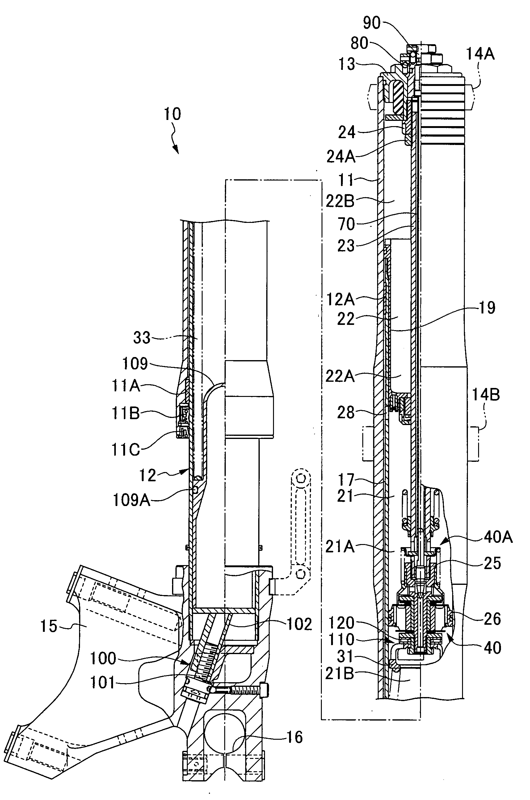
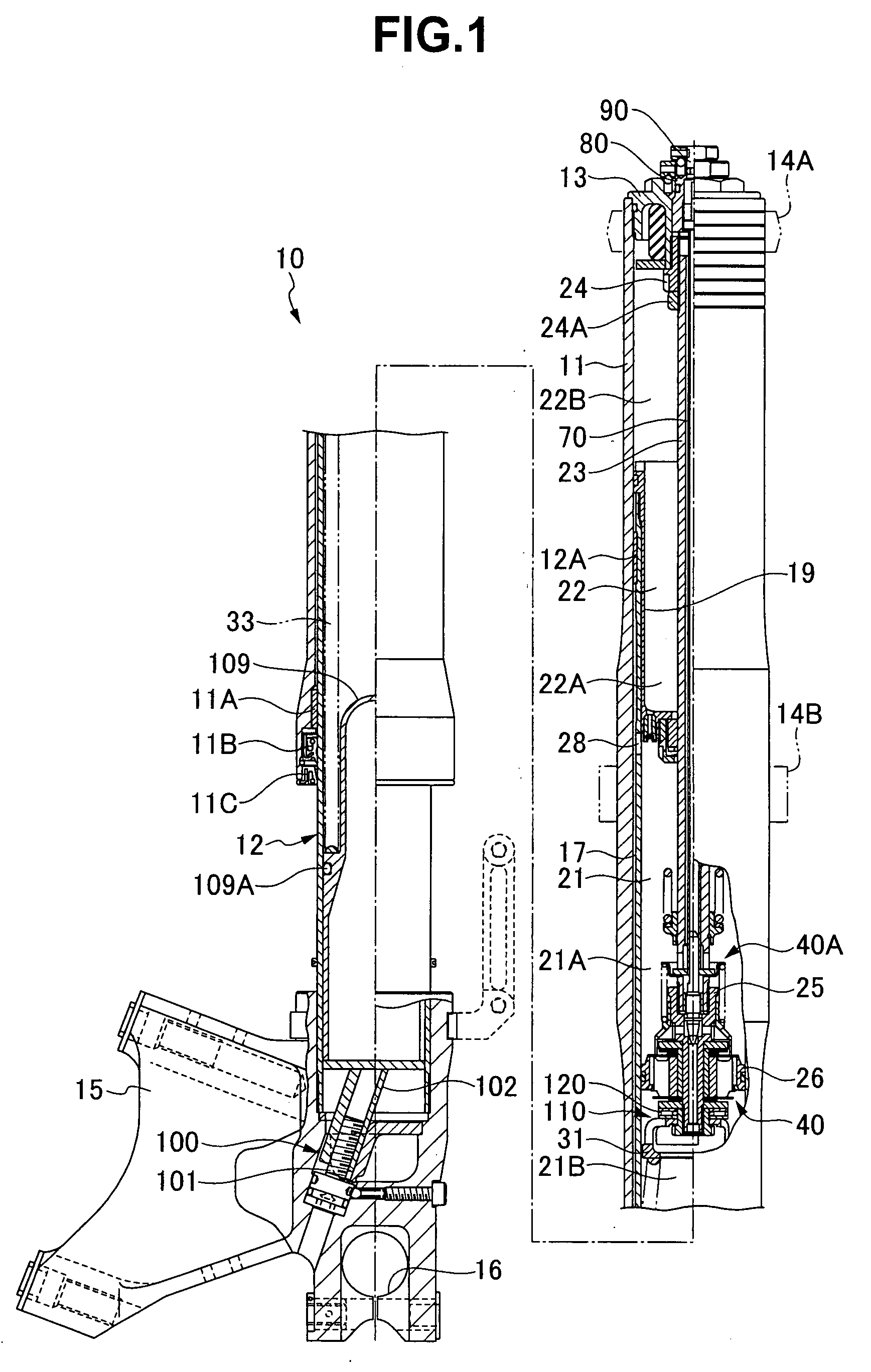
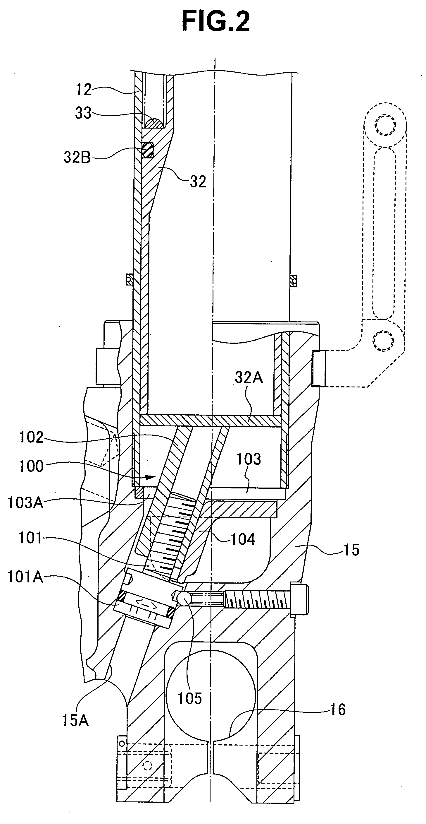
[0019]A front fork, which may be a hydraulic shock absorber, 10 is constituted by an inverted type front fork in which an outer tube 11 is arranged in a vehicle body side, and an inner tube 12 is arranged in a wheel side, and is structured, as shown in FIGS. 1 to 4. The inner tube 12 is slidably inserted to an inner portion of the outer tube 11 via a guide bush 11A fixed to an inner periphery of a lower end opening portion of the outer tube 11. A guide bush 12A is fixed to an outer periphery of an upper end opening portion of the inner tube 12. Reference numeral 11B denotes an oil seal, and reference numeral 11C denotes a dust seal. A cap 13 is screwed to the upper end opening portion of the outer tube 11 in a liquid tight manner. Vehicle body side mounting members 14A and 14B are provided in an outer periphery of the outer tube 11. An axle bracket 15 is inserted and attached to the lower end opening portion of the inner tube 12 in a liquid tight manner so as to construct a bottom p...


PUM


Abstract

In a hydraulic shock absorber in which an inner tube in an axle side is slidably inserted into an outer tube in a vehicle body side, a partition wall member is provided in an inner periphery of the inner tube, a working fluid chamber is comparted on a lower side of the partition wall member, an oil reservoir chamber is comparted on an upper side of the partition wall member, and a piston rod is attached to the outer tube side is inserted into the working fluid chamber through the partition wall member. A piston sliding within the working fluid chamber is provided in a leading end portion of the piston rod, and a suspension spring is interposed between an upper spring bearing in the piston rod side and a lower spring bearing in a bottom portion side of the inner tube, within the working fluid chamber of the inner tube. The upper spring bearing is attached to the leading end portion of the piston rod with the leading end being closer to the suspension spring than the piston in such a manner as to be rotatable and to be prevented from falling away.

Description

BACKGROUND OF THE INVENTION[0001]1. Field of the Invention[0002]The present invention relates to a hydraulic shock absorber for a vehicle.[0003]2. Description of the Related Art[0004]Regarding a hydraulic shock absorber for a vehicle, as described in Japanese Patent Publication (JP-B) No. 63-23957 (patent document 1), there is a structure in which an inner tube in an axle side is slidably inserted into an outer tube in a vehicle body side. A partition wall member is provided in an inner periphery of the inner tube. A working fluid chamber is comparted on a lower side of the partition wall member. An oil reservoir chamber is comparted on an upper side of the partition wall member. A piston rod attached to the outer tube side is inserted into the working fluid chamber through the partition wall member. A piston sliding within the working fluid chamber is provided in a leading end portion of the piston rod, and a suspension spring is interposed between an upper spring bearing in the pi...

Claims


Application Information

Patent Timeline
IPC IPC(8): F16F9/00
CPCF16F13/007F16F1/121
Inventor MURAKAMI, YOSUKE
Owner SHOWA CORP
Why Eureka
Eureka Blog
Learn More