

Push switch
- Summary
- Abstract
- Description
- Claims
- Application Information
AI Technical Summary
Benefits of technology
Problems solved by technology
Method used
Image

Examples
Embodiment Construction
[0016] Reference will now be made to the drawing figures to describe the present invention in detail.
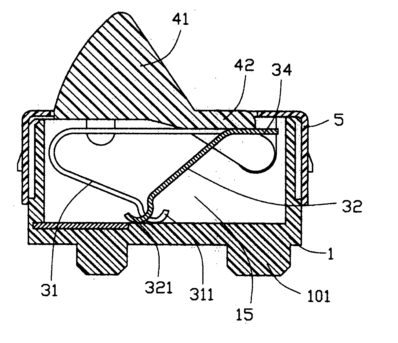
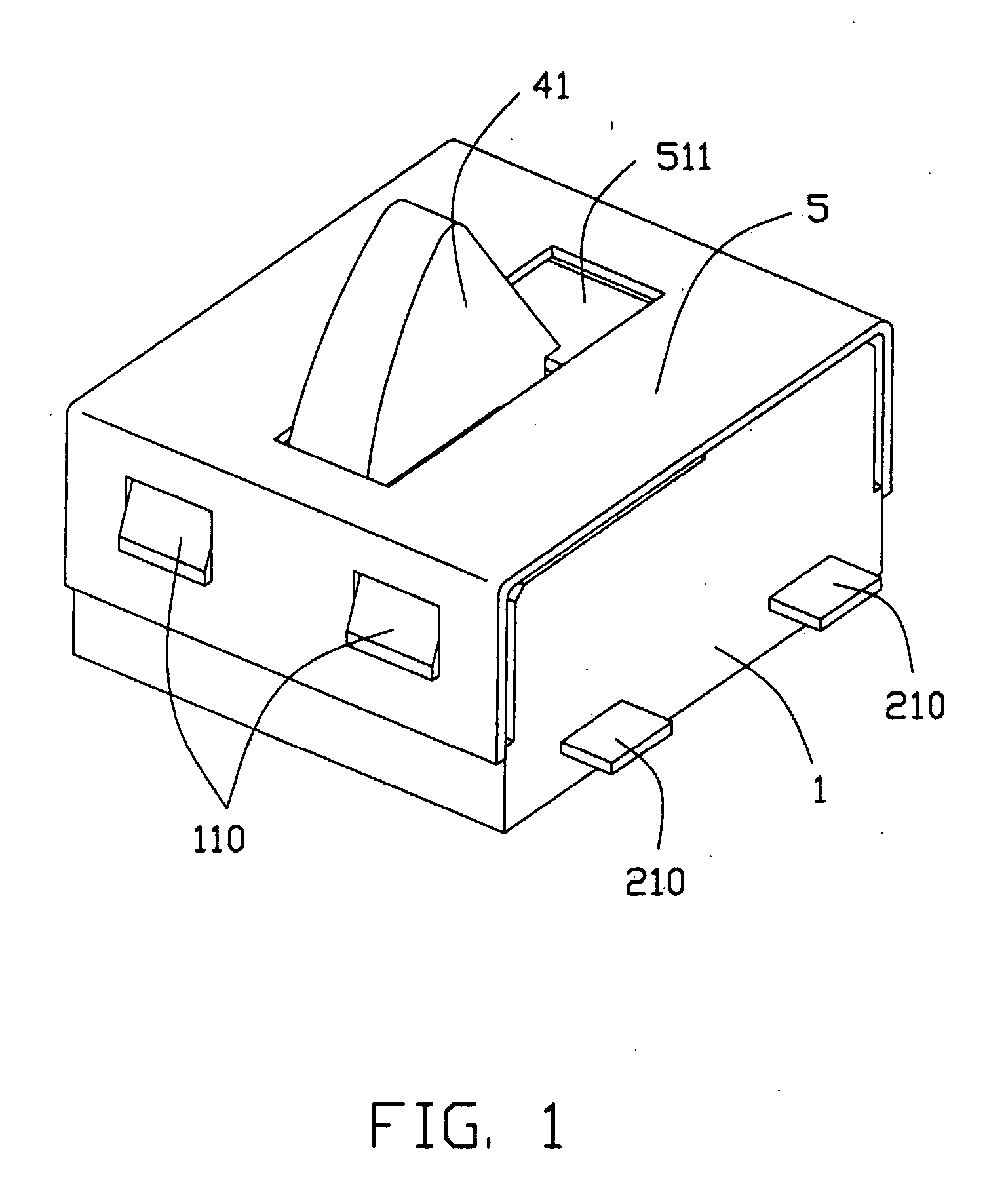
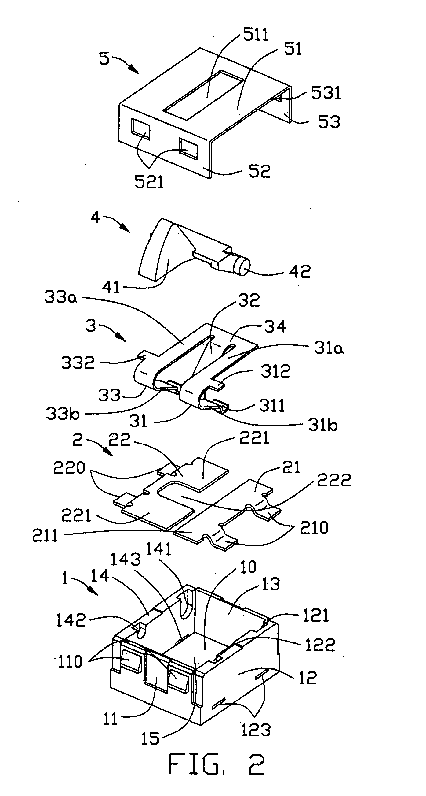
[0017] With reference to FIGS. 1 to 5, a push switch in accordance with the present invention comprises an insulating housing 1, a pair of fixed terminals 2, a moveable contact 3, an actuator 4 and a cover 5.
[0018] The insulative housing 1 made of insulative material has a base 10 and a plurality of periphery walls extending upwardly from the base 10 to thereby define a cavity 15 therebetween. The periphery walls comprise opposite front and rear walls 11, 13 and opposite right and left walls 12, 14. Two pairs of protrusions 110, 130 are formed on the outside of the front and rear walls 11, 13. A pair of first recesses 121, 141 and a pair of second recesses 122, 142 are respectively and symmetrically defined in an inner surface of the right and left walls 12, 14. Two pairs of slits 123, 143 corresponding to the fixed terminals 2 are respectively defined through the lower part of the...
PUM
 Abstract
Description
Claims
Application Information