Stirling engine

A Stirling engine and reciprocating motion technology, applied to refrigerators, compressors, lighting and heating equipment, etc., can solve the problems of indispensable performance testing and difficult readjustment, and achieve improved assembly, reliability, and Ease of improvement effect

Inactive Publication Date: 2006-08-16
SHARP KK
View PDF3 Cites 5 Cited by
  • Summary
  • Abstract
  • Description
  • Claims
  • Application Information

AI Technical Summary

Problems solved by technology

Therefore, there is no lack of performance testing for each unit
however, the structural elements of a Stirling

Method used


Image

  • Stirling engine
  • Stirling engine
  • Stirling engine

Examples


Example Embodiment

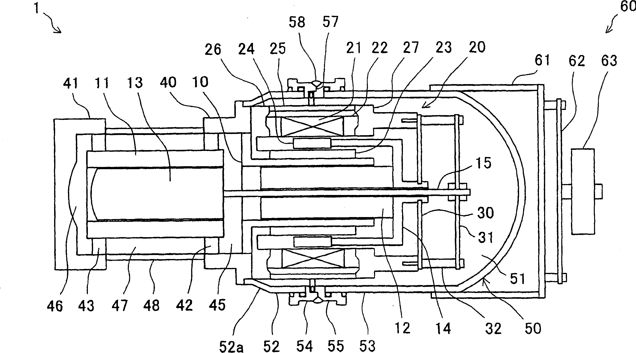
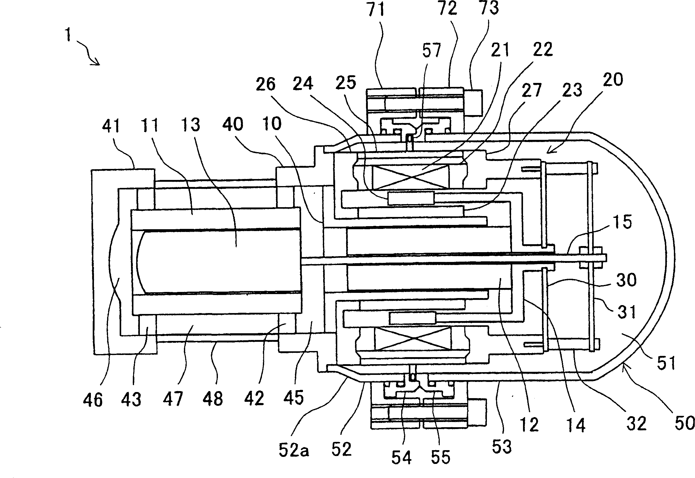
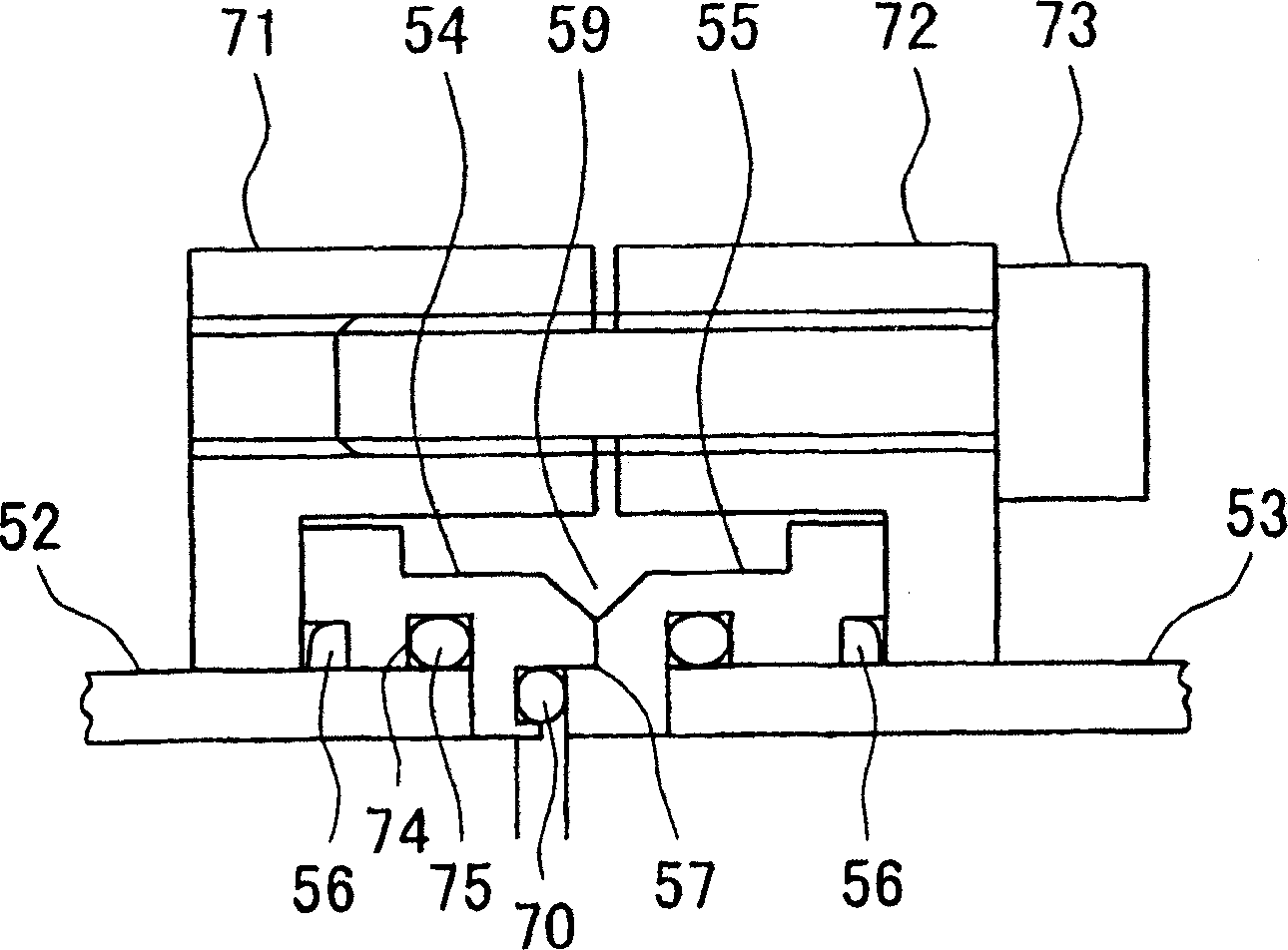
[0044] Embodiments of the present invention will be described below with reference to the drawings. Figure 1-Figure 3 represents the first embodiment. figure 1 It is a sectional view of the finished product of the Stirling engine, figure 2 is a cross-sectional view of the temporary bonding stage, image 3 Yes figure 2 The enlarged view of the main part.

[0045] Central to the assembly of the Stirling engine 1 are the pressure cylinders 10 , 11 . The axes of the pressure cylinders 10, 11 are aligned on the same straight line. A piston 12 is inserted into the pressure cylinder 10 , and a displacer 13 is inserted into the pressure cylinder 11 . During the operation of the Stirling engine 1 , the piston 12 and the displacer 13 reciprocate without contacting the pressure cylinders 10 and 11 by the structure of the gas bearing.

[0046] One end of the piston 12 is fixed with a cup-shaped magnet holder 14 . A displacer shaft 15 protrudes from one end of the displacer 13 . ...


PUM


Abstract

In a Stirling engine, a hollow cylinder-like pressure vessel covers a cylinder, a piston, and a linear motor. The pressure vessel is divided into a ring-like portion and a dome-like portion at a position closer to the displacer installation side than a piston support-side end of the linear motor. At the divided portion, an outward-facing flange-shaped portion is formed for each of the ring-like portion and the dome-like portion. For temporary sealing of the pressure vessel, both flange-shaped portions are joined together and tightened by tightening rings and bolts. A performance check is performed in this state, and then outer peripheral portions of the flange-shaped portions are welded together for final sealing.

Description

technical field [0001] The present invention relates to Stirling engines, in particular Stirling engines of the free-piston type. Background technique [0002] The Stirling engine has attracted attention as a heat engine that does not deplete the ozone layer because it uses helium, hydrogen, nitrogen, etc., instead of Freon, as its working gas. Examples of Stirling engines can be seen in Patent Documents 1-3. [0003] Patent Document 1: JP-A-2000-337725 (pp. 2-4, figure 1 ) [0004] Patent Document 2: JP-A-2001-231239 (pp. 2-4, figure 1 ) [0005] Patent Document 3: JP-A-2002-349347 (pp. 5-6, figure 1 ) [0006] The Stirling engine has not yet reached mass production. For mass production, it is necessary to at least improve assembly performance to ensure quality stability after assembly. [0007] The operation of the Stirling engine is based on a delicate balance, and proper and careful design and assembly adjustment are required in order to exhibit desired performan...

Claims


Application Information

Patent Timeline
IPC IPC(8): F25B9/14
Inventor 吉村和士高井健二北村义之山上真司坂元仁安村浩至
Owner SHARP KK
Why Eureka
Try Eureka