Power transmission device for vehicle

A power transmission device, vehicle technology, applied in the direction of control device, vehicle components, transportation and packaging, etc., to achieve the effect of reducing weight and cost

Inactive Publication Date: 2014-08-06
HONDA MOTOR CO LTD
View PDF8 Cites 3 Cited by
  • Summary
  • Abstract
  • Description
  • Claims
  • Application Information

AI Technical Summary

Problems solved by technology

In a hybrid vehicle equipped with both an engine and a motor generator as driving sources for traveling, the engine can be started using the motor generator as a starter motor, but a dedicated starter motor is still required in a vehicle without a motor generator

Method used


Image

  • Power transmission device for vehicle
  • Power transmission device for vehicle
  • Power transmission device for vehicle

Examples


Embodiment Construction

[0049] Below, based on Figure 1 to Figure 9 Embodiments of the present invention will be described.

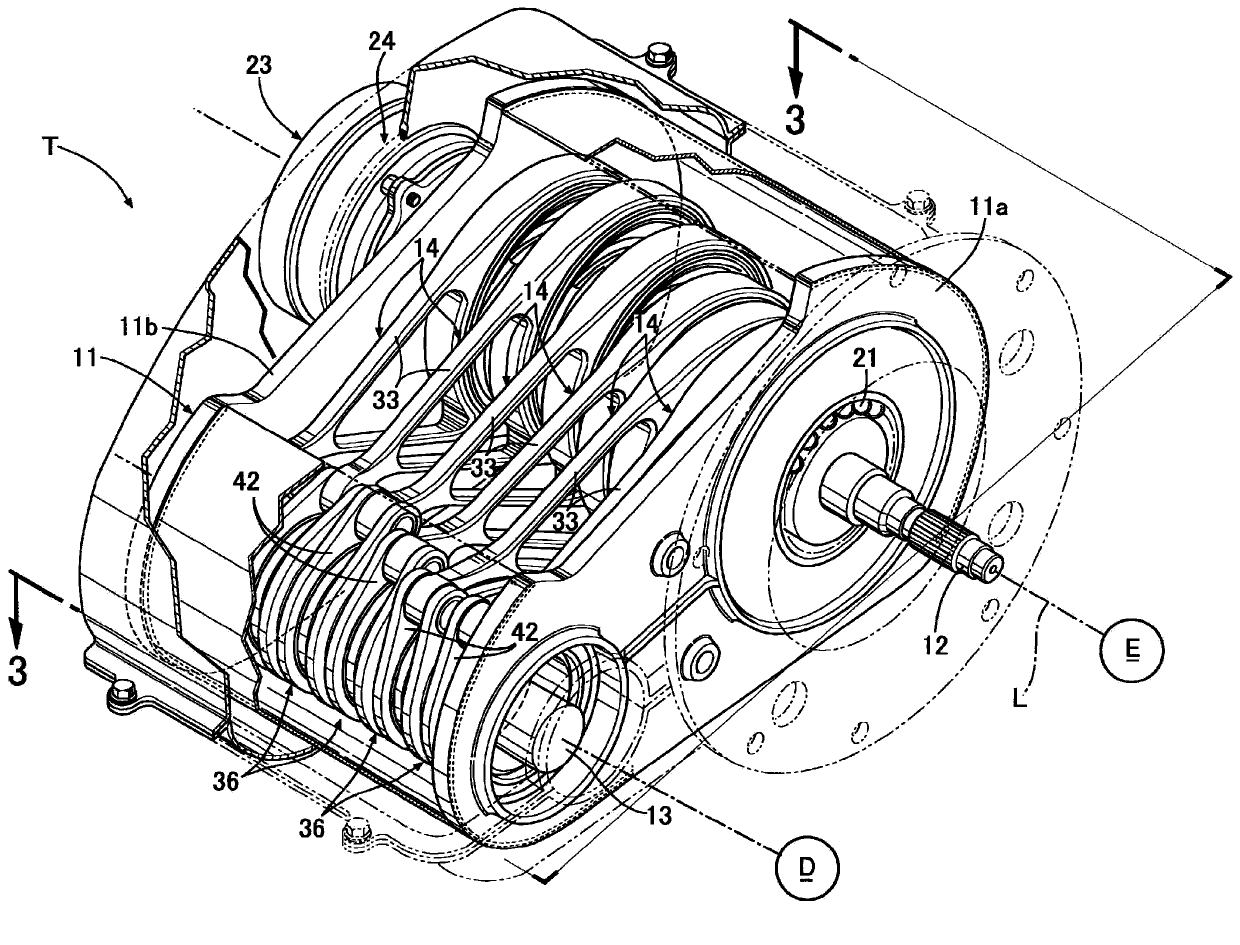
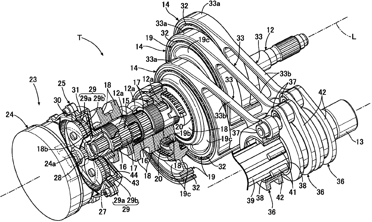
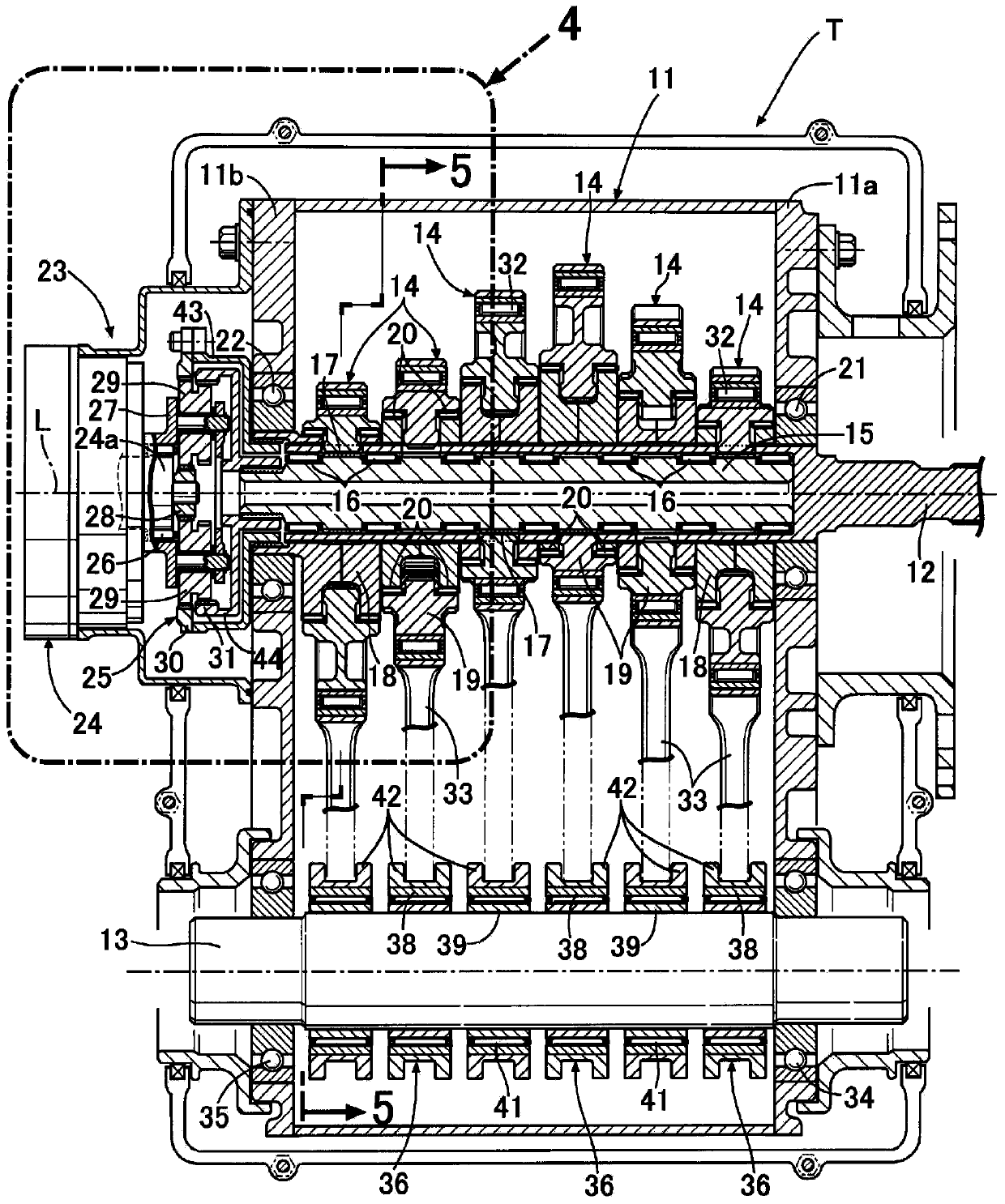
[0050] Such as Figure 1 to Figure 5 As shown, the input shaft 12 and the output shaft 13 are supported on a pair of side walls 11a, 11b of the transmission case 11 of the continuously variable transmission T for motor vehicles in parallel with each other, and the rotation of the input shaft 12 connected to the engine E passes through six The transmission unit 14 . . . , the output shaft 13 and the differential D transmit to the drive wheels. A transmission shaft 15 sharing an axis L with the input shaft 12 is relatively rotatably fitted inside the hollow input shaft 12 via seven needle bearings 16 . . . . The configurations of the six transmission units 14... are substantially the same, and therefore, the configuration will be described below using one transmission unit 14 as a representative.

[0051] The transmission unit 14 includes a pinion 17 provided on the outer pe...


PUM


Abstract

The invention provides a power transmission device for a vehicle. The power transmission device can start an engine by using an electric motor for driving a variable speed actuator. When the electric motor (24) is used to drive a sun gear (28) of a planetary gear mechanism (25) of the variable speed actuator (23) to rotate, a first gear ring (30) and a second gear ring (31) rotate relatively; and a first connecting portion (43a) of a first connecting component (43) integrated with an input shaft (12) is connected to a second connecting portion (44a) of a second connecting component (44) with a variable speed shaft (12), so the input shaft and the variable speed shaft (12) are driven to rotate integrally by a driving force of the electric motor. Therefore, the driving force of the electric motor enables the engine connected to the input shaft to rotate and start, a starting motor can be omitted, or low capacity starting motor can be used to reduce weight and cost. Meanwhile, the engine can be started smoothly by using the driving force of the electric motor assists to the driving force of the starting motor.

Description

technical field [0001] The present invention relates to a power transmission device for a vehicle capable of starting an engine by using an electric motor that drives a transmission actuator. Background technique [0002] According to the following patent document 1, there is known a continuously variable transmission that converts the rotation of an input shaft connected to an engine into reciprocating motions of a plurality of connecting rods with different phases, and uses a plurality of one-way clutches to connect the plurality of connecting rods to each other. The reciprocating motion of the output shaft is converted into the rotary motion of the output shaft. [0003] Patent Document 1: Japanese PCT Publication No. 2005-502543 [0004] However, in a vehicle that uses an engine as a drive source for traveling, a starter motor for starting the engine is required. In a hybrid vehicle having both an engine and a motor generator as drive sources for traveling, the engine ...

Claims


Application Information

Patent Timeline
Patent Type & Authority Applications(China)
IPC IPC(8): B60K17/06
Inventor 市川和树西村优史
Owner HONDA MOTOR CO LTD
Why Eureka
Try Eureka