Working vehicle

a technology for working vehicles and trucks, applied in mechanical machines/dredgers, soil shifting machines/dredgers, transportation and packaging, etc., can solve the problems of increasing the cost of manufacturing, and achieve the effect of smooth engine star

Inactive Publication Date: 2010-07-20
YANMAR POWER TECHNOLOGY CO LTD
View PDF12 Cites 35 Cited by
  • Summary
  • Abstract
  • Description
  • Claims
  • Application Information

AI Technical Summary

Benefits of technology

[0010]Accordingly, since it is possible to inhibit the load from being propagated to each of the cases as well as it is possible to improve the support strength serving as a whole of the traveling vehicle body with respect to the transmission case and the rear axle case, it is not necessary to thicken each of the cases themselves, and it is possible to avoid the cases from being made large in size. As a result, it is possible to achieve an effect of contributing to a suppression of a manufacturing cost.
[0013]In accordance with the structure mentioned above, as far as the control seat is backward directed, the engine stop mechanism becomes out of commission regardless of whether or not the operator is seated, and the engine maintains a drive state. Accordingly, in spite of the working vehicle having the seating detecting means and taking a safety into consideration, there can be achieved an effect that it is possible to smoothly start the engine at a time of the excavating work by the backhoe which is carried out in a state of directing the control seat backward.

Problems solved by technology

Therefore, in the conventional structure mentioned above, since there is a risk that the load generated at a time of traveling in the backhoe installed state or at a time of the excavating work by the backhoe is propagated to the transmission case, it is necessary to thicken the transmission case for securing a strength.
As a result, there is a problem that the mission case is made large in size and heavy and the vehicle body frame itself supporting the transmission case is made large in size and heavy, so that a manufacturing cost is increased.

Method used


Image

  • Working vehicle
  • Working vehicle
  • Working vehicle

Examples


Embodiment Construction

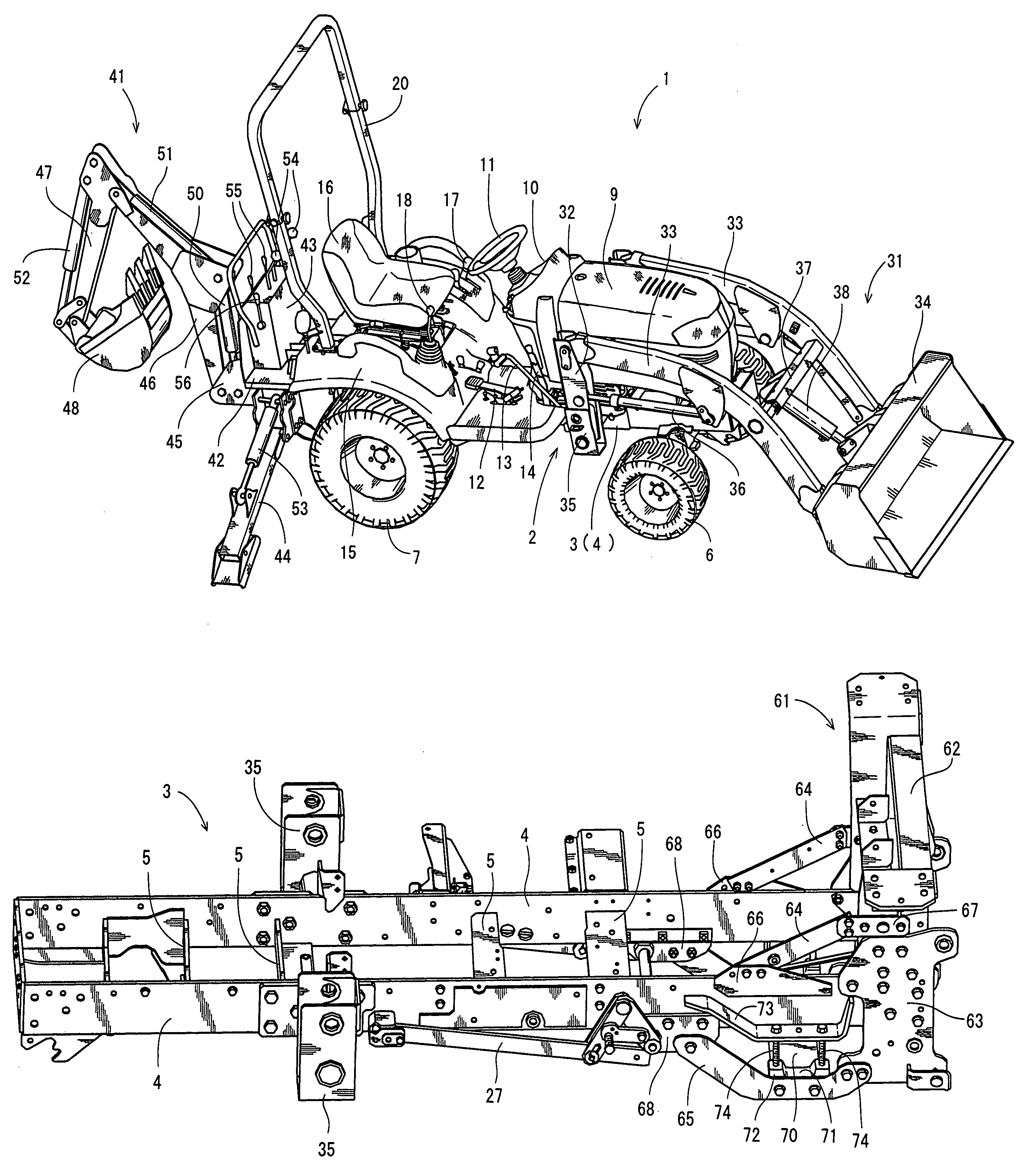
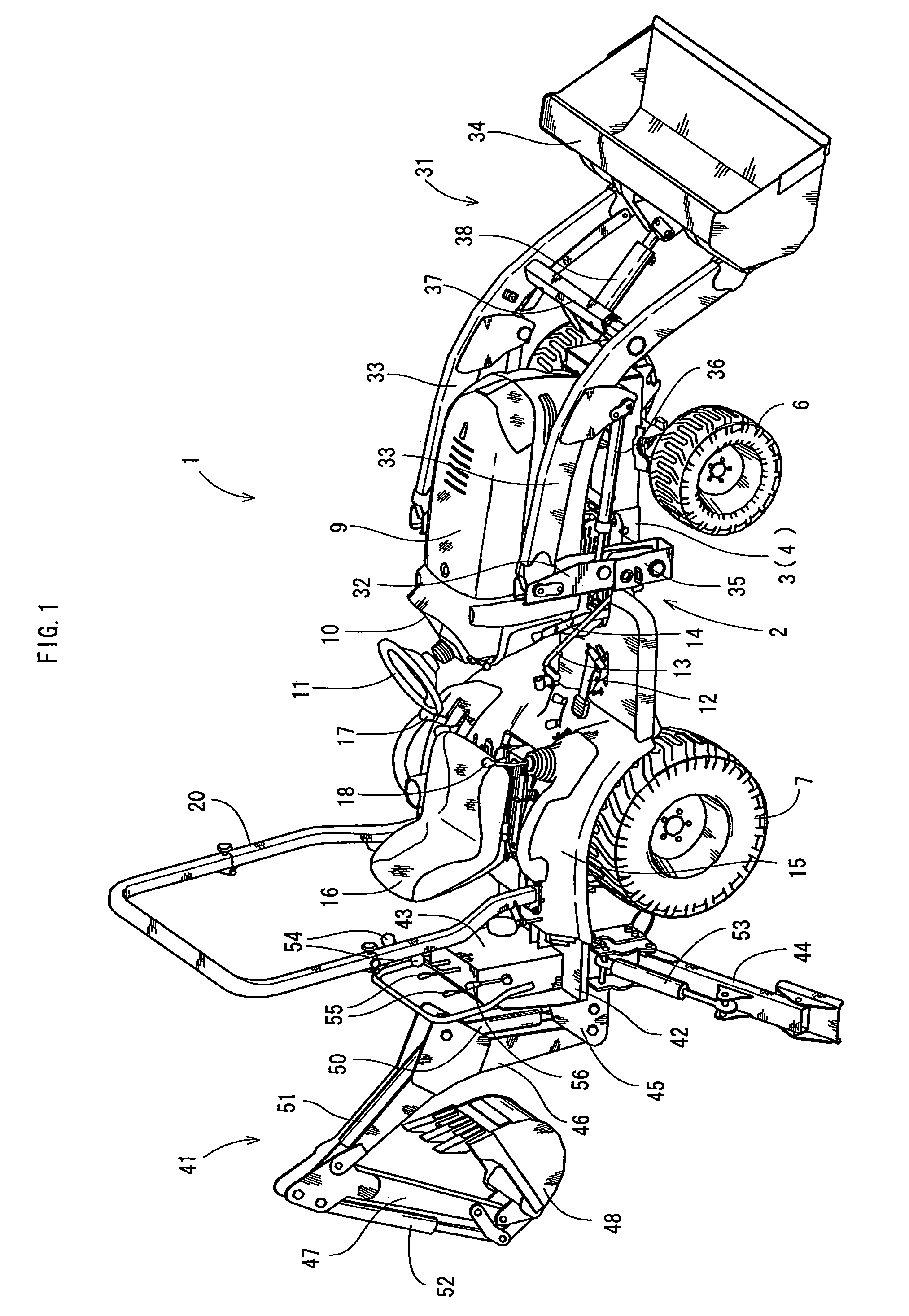
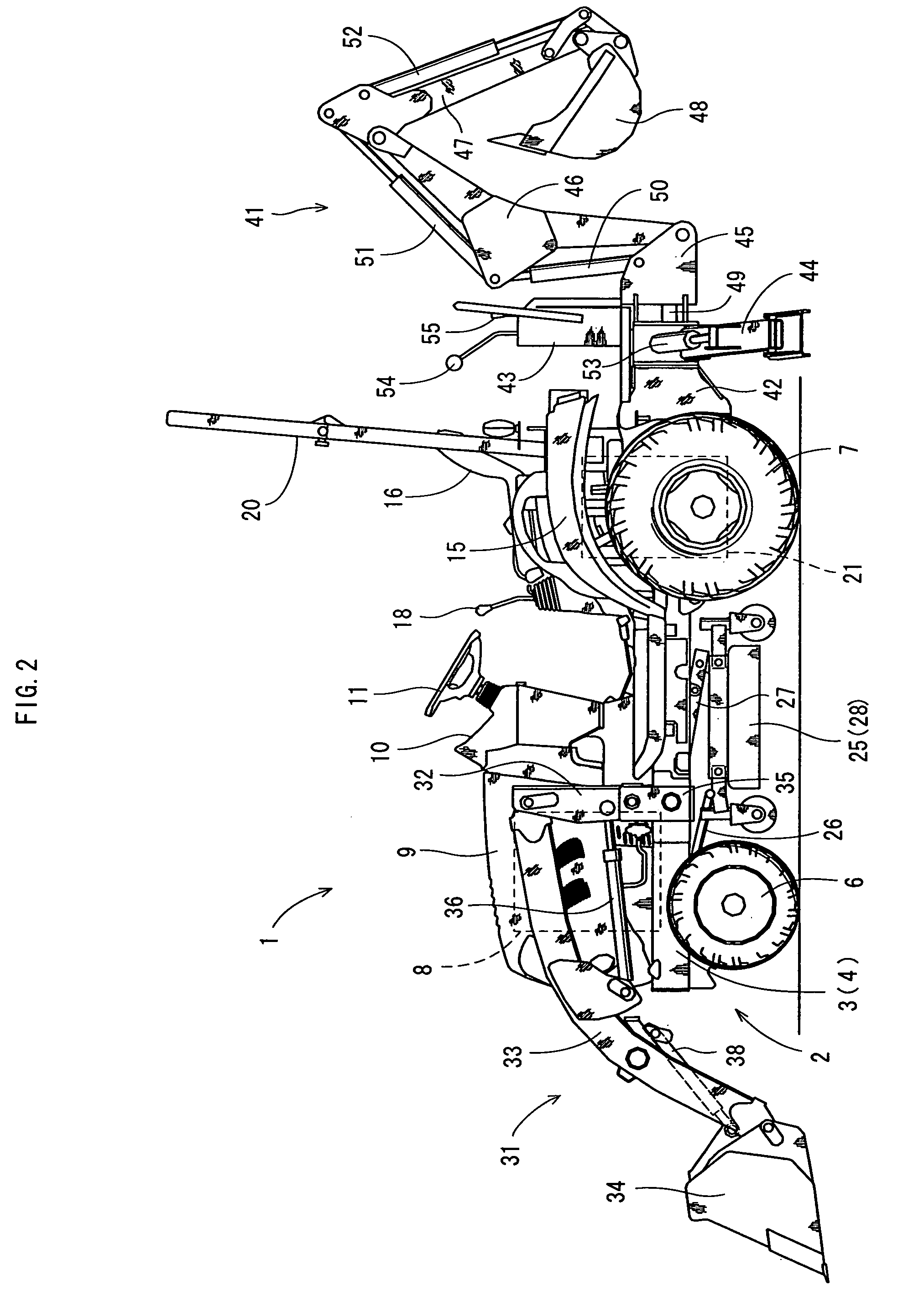
[0027]A description will be given of an embodiment in which the present invention is applied to a TLB serving as a working vehicle with reference to the accompanying drawings (FIGS. 1 to 13). FIG. 1 is a perspective view of a whole of the TLB, FIG. 2 is a left side elevational view of the TLB, FIG. 3 is a plan view of the TLB, FIG. 4 is an enlarged perspective view of a rear portion in the case of viewing the TLB from a left oblique rear side, FIG. 5 is a perspective view in the case of viewing a vehicle body frame from a left oblique upper side, FIG. 6 is a perspective view in the case of viewing the vehicle body frame from a right oblique lower side, FIG. 7 is an enlarged perspective view in the case of viewing the vehicle body frame with a transmission case from a left oblique upper side, FIG. 8 is a perspective view in the case of viewing the vehicle body frame with the transmission case from a rear side, FIG. 9 is a perspective view in the case of viewing the vehicle body frame...


PUM


Abstract

In a working vehicle in which a backhoe support frame for reinforcing is provided in a rear end portion of a vehicle body frame, and a transmission case is mounted on a rear portion of the vehicle body frame so as to be close to the backhoe support frame, each of support brackets provided in an outer side surface of a rear portion of each of main frames constructing the vehicle body frame so as to protrude outward is connected to a protruding end portion protruding to rightwardly and leftwardly relative to each of lower brace members in a reinforcing plate supporting a lower surface of the transmission case in a state in which a rear axle case protruding outward from the right and left side surfaces of the transmission case is sandwiched from upper and lower sides, in order to dissolve a risk that a load generated at a time of traveling in a backhoe installed state or at a time of an excavating work by the backhoe is propagated to the transmission case.

Description

BACKGROUND OF THE INVENTION[0001]1. Field of the Invention[0002]The present invention relates to a working vehicle, for example, a tractor front loader backhoe (hereinafter, refer to as TLB).[0003]2. Description of Background Art[0004]Conventionally, in the TLB serving as the working vehicle, since various loads such as a compression, a tension, a deflection, a bending and the like are applied to a vehicle body frame constructing a traveling vehicle body in a complex manner at a time of traveling in a state in which a backhoe is installed to a rear portion of the traveling vehicle body or at a time of an excavating work by the backhoe, there is employed such a structure that a backhoe support frame for reinforcing is provided in a rear end portion of the vehicle body frame and the backhoe is installed to the backhoe support frame, for example, as described in Japanese Unexamined Patent Publication No. 6-32188.[0005]In accordance with this structure, the backhoe support frame serves ...

Claims


Application Information

Patent Timeline
Patent Type & Authority Patents(United States)
IPC IPC(8): B66C23/00
CPCE02F3/964E02F9/0808E02F9/0825E02F9/16E02F9/24
Inventor WAKUTA, KENSAKUMIYAMOTO, KAZUHIKO
Owner YANMAR POWER TECHNOLOGY CO LTD
Why Eureka
Try Eureka