Rolling device

Inactive Publication Date: 2003-10-23
NSK LTD
View PDF1 Cites 27 Cited by
  • Summary
  • Abstract
  • Description
  • Claims
  • Application Information

AI Technical Summary

Benefits of technology

0032] A first object of this invention is to provide a rolling device operating, particularly, at a high speed capable of effectively suppressing lowering of the accuracy in the repetitive positioning caused by thermal expansion of a support, wear

Problems solved by technology

However, in the linear motion guiding device disclosed in Japanese Published Unexamined Patent Application No. 175691/1987, the guide rail is formed of a ceramic material having a specific rigidity of 0.8.times.10.sup.8 mm or more and its application to the electronic part mounting apparatus or the wire bonding apparatus has been difficult by the following reasons.
On the contrary, since the linear motion guiding device disclosed in the publication above has a constitution of fixing both ends of the guide rail on the supporting bed or the like and moving the slider in use, it is not suitable to the application to the electronic part mounting apparatus or wire bonding apparatus described above.
Further, when a large bending moment is loaded on the guide rail, the guide rail is fractured in a case where the bending strength is insufficient even if the constituent material therefor is alumina ceramics, silicon carbide ceramics or silicon nitride.
Accordingly, it is difficult to increase the speed of the apparatus by merely forming the guide rail of ceramics regarding the reliability in view of the strength(particularly, reliability to bending strength).
Accordingly, it is difficult to increase the speed of the apparatus by merely constituting the guide rails with ceramics in view of the reliability for the strength (particularly, bending strength).
Further, while the rigidity of the rail per se is increased by forming the rail material of ceramic material, surface contact pressure with a rolling member incorporated in a slider increases, which increases the load on the rolling member compared with a case of using a rail formed of steels.
For example, when silicon nitride is used as the rail material and the rolling element is constituted with martensitic stainless steel, a difference of twice or more is caused for the hardness between them and wear of the rolling element is sometimes accelerated compared with a case of using a rail formed of steels.
However, when the guide rail rotates while moving vertically at a high speed as in the electronic part mounting apparatus or wire bonding apparatus, large inertia force is generated by acceleration or own weight of the rail and the head weight, and the driving performance(cycle speed, response performance) is deteriorated by the inertia force.
Further, since the inertia force is also increased when the density(mass) of the guide rail is large in this case, the bending strength of the guide rail is insufficient to sometimes result in fracture even in a case of using the cermet or cemented carbide as the rail material.
Further, when the ceramic material(particularly, usual silicon nitride) is used as the rail material, the heat conductivity is low and heat tends to be accumulated in the inside of the apparatus.
That is, when the guide rail is formed of a ceramic material of poor heat conductivity such as silicon nitride, since the temperature on the sliding surface of the guide rail becomes higher during operation and the grease viscosity lowers due to the temperature elevation on the rail sliding surface compared with a case of using iron and steel material such as bearing steels as the rail material, formation of oil membranes between the rolling element and the surface of the rail groove is inhibited to cause wear or minute seizure of the rolling element.
They cause generation of vibrations during operation of the linear motion guiding device, giving undesired effects on the accuracy in the repetitive positioning.
Further, temperature elevation of the rail material accelerates thermal expansion of the guide rail, which also gives undesired effects on the accuracy in the repetitive positioning.
Further, in view of increase in the diameter of wafers or liquid crystal panels, it results in the requirement for the rolling device to support larger load.
However, in the rolling bearing described in Japanese Published Unexamined Patent Application No. 121488/1996, since the outer ring is manufactured by an atmospheric pressure sinte

Method used


Image

  • Rolling device
  • Rolling device
  • Rolling device

Examples


Example

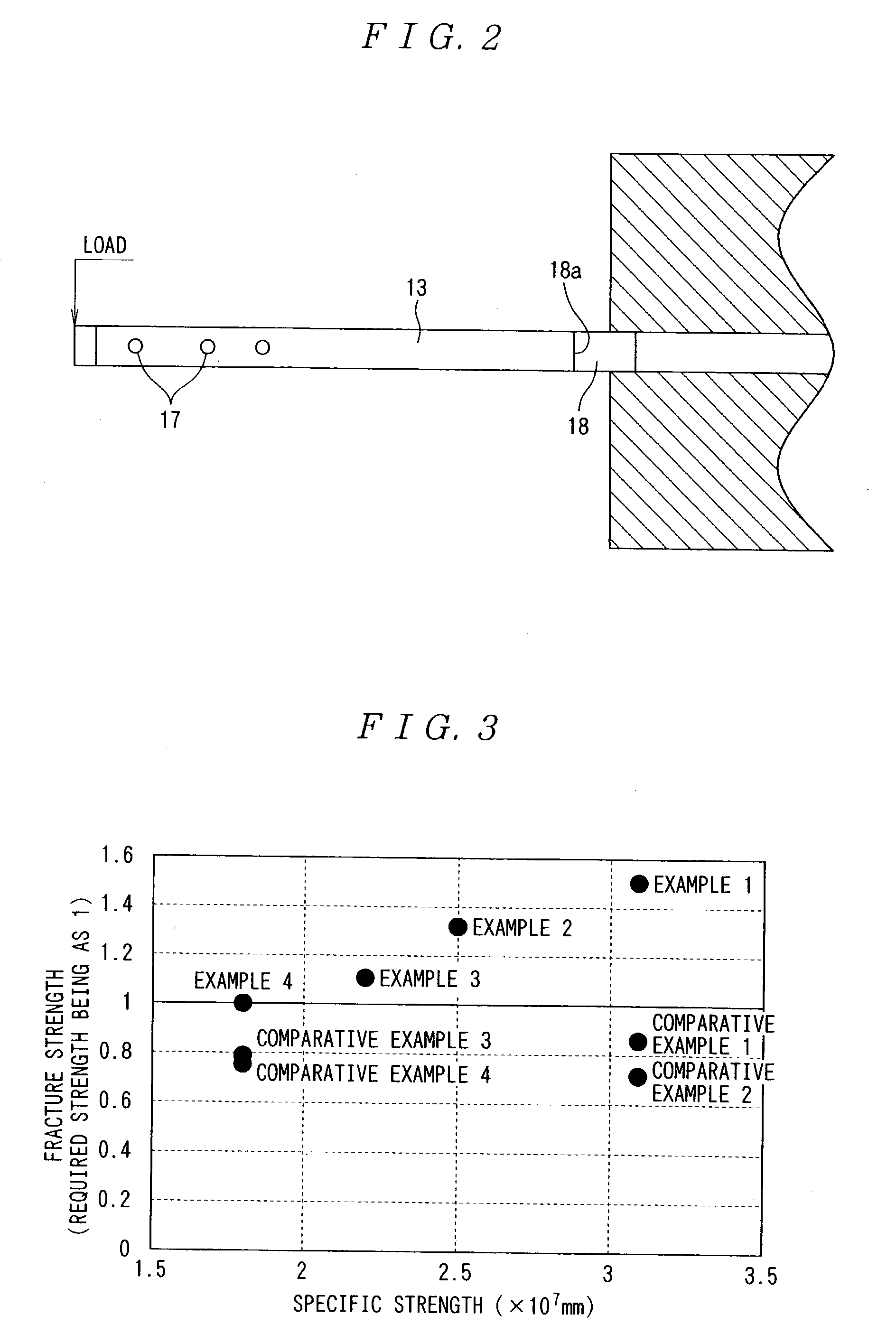
[0181] In Table 1 and Table 2, a guide rail of Example 1 used high strength silicon nitride obtained by press sintering at 1000 atm or higher (specific strength: 3.1.times.10.sup.7 mm) as the rail material in which a surface roughness for the rail planar part was 0.3 .mu.mRa, the surface roughness of the rolling groove 16 of rolling element was 0.08 .mu.mRa and a radius of curvature at the corner 18a of the recess 18 as R=about 0.15 mm. Further, the guide rail of Example 2 used a silicon nitride obtained by press sintering at about 100 atm or higher (specific strength: 2.5.times.10.sup.7 mm) as the rail material in which a surface roughness for the rail planar part was 0.3 .mu.mRa, the surface roughness of the rolling groove 16 of rolling element was 0.08 .mu.mRa and a radius of curvature at the corner 18a of the recess 18 was: R=0.15 mm.

Example

[0182] The guide rail of Example 3 used a silicon nitride obtained by press sintering under sintering condition at 10 atm or lower (specific strength: 2.2.times.10.sup.7 mm) as the rail material in which a surface roughness for the rail planar part was 0.4 .mu.mRa, a surface roughness of the rolling groove 16 of rolling element was 0.08 .mu.mRa and a radius of curvature at the corner 18a of the recess 18 was R=0.15 mm. Further, the guide rail of Comparative Example 1 used high strength silicon nitride (specific strength: 3.1.times.10.sup.7 mm) as a rail material in which a surface roughness for the rail planar part was 0.6 .mu.mRa, a surface roughness for the rolling groove 16 of rolling element was 0.08 .mu.mRa and the radius of curvature at the corner 18a of the recess 18 was: R=0.15 mm.

Example

[0183] The guide rail of Example 4 used silicon nitride sintered at 10 atm or lower (specific strength: 1.8.times.10.sup.7 mm) as a rail material in which a surface roughness for the rail planar part was 0.3 .mu.mRa, a surface roughness for the rolling groove 16 of rolling element was 0.08 .mu.mRa and a radius of curvature for the corner 18a of the recess 18 was R=0.15 mm.


PUM

PropertyMeasurementUnit
Pressureaaaaaaaaaa
Pressureaaaaaaaaaa
Percent by volumeaaaaaaaaaa

Abstract

A guide rail 13 is formed of a ceramic material having a specific strength of 2x10<7 >mm or more and has a planar part with a surface roughness of 0.5 mumRa or less. Further, the guide rail 13 has a recess 18 for avoiding interference with a part to be attached in which the corner 18a of the recess 18 is formed with a radius of curvature of 0.1 mm or more.

Description

TECHNICAL FIELDS[0001] This invention relates to a rolling device such as a rolling bearing, a linear motion guiding device or a ball screw and, more in particular, it relates to a rolling device that can be used under high load at high speed, in a corrosive circumstance, high temperature circumstance or in a circumstance supporting a radial load, such as in various kinds of spindles, various kinds of pumps, semiconductor production apparatus (transportation apparatus and the like), machine tools and turbines.[0002] Electronic part mounting apparatus used, for example, in the process of producing electronic equipments such as computers or mobile telephones are adapted, for example, such that an electronic part suction head is disposed vertically movably above an X-Y table on which a substrate is placed and electronic parts are mounted at predetermined positions on the substrate by sucking electronic parts such as semiconductor devices by the head. Accordingly, for mounting electroni...

Claims


Application Information

Patent Timeline
IPC IPC(8): F16C29/00F16C33/30F16C33/32F16C33/34F16C33/62
CPCF16C29/005F16C33/32F16C33/34F16C33/62F16C2206/82F16C2206/00F16C2206/60F16C2206/80F16C2240/48F16C2220/20F16C2240/54
Inventor YAMAMOTO, TOYOHISAIKEDA, NORIFUMIYAMAMOTO, KOUICHI
Owner NSK LTD
Why Eureka
Try Eureka