Package method of inkjet-printhead chip and its structure

Inactive Publication Date: 2008-05-22
NAT SYNCHROTRON RADIATION RES CENT
View PDF2 Cites 5 Cited by
  • Summary
  • Abstract
  • Description
  • Claims
  • Application Information

AI Technical Summary

Benefits of technology

[0006]In order to solve the foregoing problems, one object of this invention is to provide a package method of the inkjet-printhead chip a

Problems solved by technology

Therefore, the demands of the package and bonding technique for the inkjet-printhead chip are getting stricter.
However, it is necessary to use an excimer laser to

Method used


Image

  • Package method of inkjet-printhead chip and its structure
  • Package method of inkjet-printhead chip and its structure
  • Package method of inkjet-printhead chip and its structure

Examples


Embodiment Construction

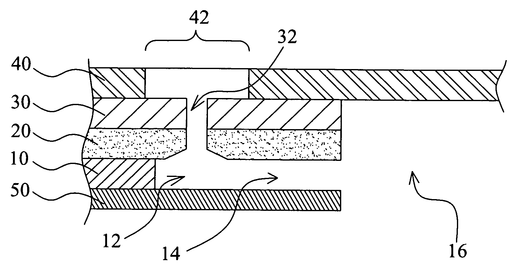
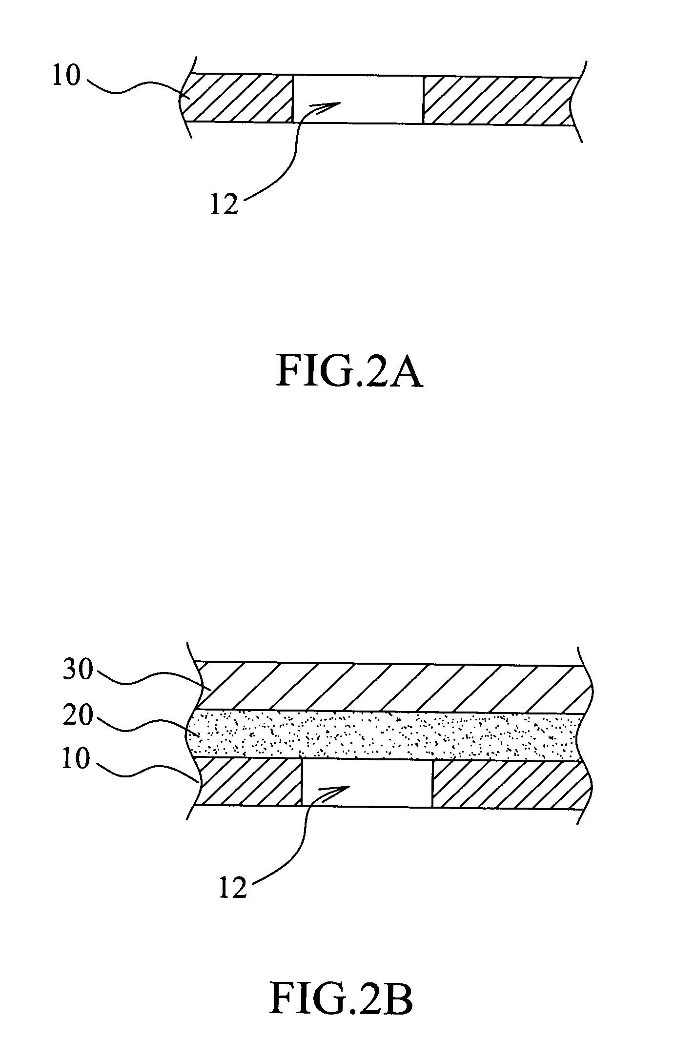
[0014]FIG. 2A to FIG. 2E are the schematic cross-sectional diagrams illustrating the procedures of the package method of the inkjet-printhead chip in accordance with one embodiment of the present invention. At first, please refer to FIG. 2D, which is a package structure of the inkjet-printhead chip of the present invention. As shown in the FIG. 2D, the package structure of the inkjet-printhead chip includes a nozzle structure of a print element, and the nozzle structure includes an ink chamber layer 10, a nozzle base layer 20 and a nozzle layer 30, wherein the nozzle base layer 20 is optional and depends on the case. A plurality of nozzle through holes 32 pass through the nozzle base layer 20 and the nozzle layer 30 to connect with an ink chamber 12 of the ink chamber layer 10. A flexible substrate 40 with at least an opening 42 is set on the nozzle layer 30, and the opening 42 corresponds to and exposes the nozzle through holes 32. A chip 50 is set under the ink chamber layer 10.

[0...


PUM

PropertyMeasurementUnit
Adhesion strengthaaaaaaaaaa
Flexibilityaaaaaaaaaa
Areaaaaaaaaaaa

Abstract

The present invention discloses a package method of the inkjet-printhead chip and its structure. The structure includes: a nozzle structure of a print element including an ink chamber layer and a nozzle layer on the ink chamber layer, wherein a plurality of nozzle through holes are set in the nozzle layer and pass through an ink chamber of the ink chamber layer; a flexible substrate set on the nozzle layer, wherein there is at least an opening set in the flexible substrate to expose those nozzle through holes; and a chip set under the ink chamber layer. Besides, the present package method is to utilize the micro-manufacturing process to form the nozzle structure of a print element and the tape automatic bonding process to bond the flexible substrate on the nozzle layer and the chip under the ink chamber layer.

Description

BACKGROUND OF THE INVENTION[0001]1. Field of the Invention[0002]The present invention relates to a package method of a chip and its structure, and more especially, to the package method of the inkjet-printhead chip and its structure.[0003]2. Background of the Related Art[0004]The inkjet-printhead is the key component of the inkjet printer. The reliability, the density of the spurted holes and the small size are increasingly demanded for the package structure of the inkjet-printhead chip due to the demands of high printing quality and high resolution. Therefore, the demands of the package and bonding technique for the inkjet-printhead chip are getting stricter.[0005]FIG.1 is a cross-sectional schematic diagram illustrating the inkjet-printhead structure of the U.S. Pat. No. 5,420,627, and it discloses the ink cartridge with edge feed design, which is widely utilized in the wide format, commercial and desktop printer. The advantage of the inkjet-printhead 100 is to cool the heating ch...

Claims


Application Information

Patent Timeline
IPC IPC(8): B41J2/16
CPCB41J2/1603Y10T29/49401B41J2/1623B41J2/162
Inventor LINLIU, KUNG
Owner NAT SYNCHROTRON RADIATION RES CENT
Why Eureka
Try Eureka