

Assembled crankshaft and method for making crankshaft assembly
- Summary
- Abstract
- Description
- Claims
- Application Information
AI Technical Summary
Benefits of technology
Problems solved by technology
Method used
Image

Examples
Embodiment Construction
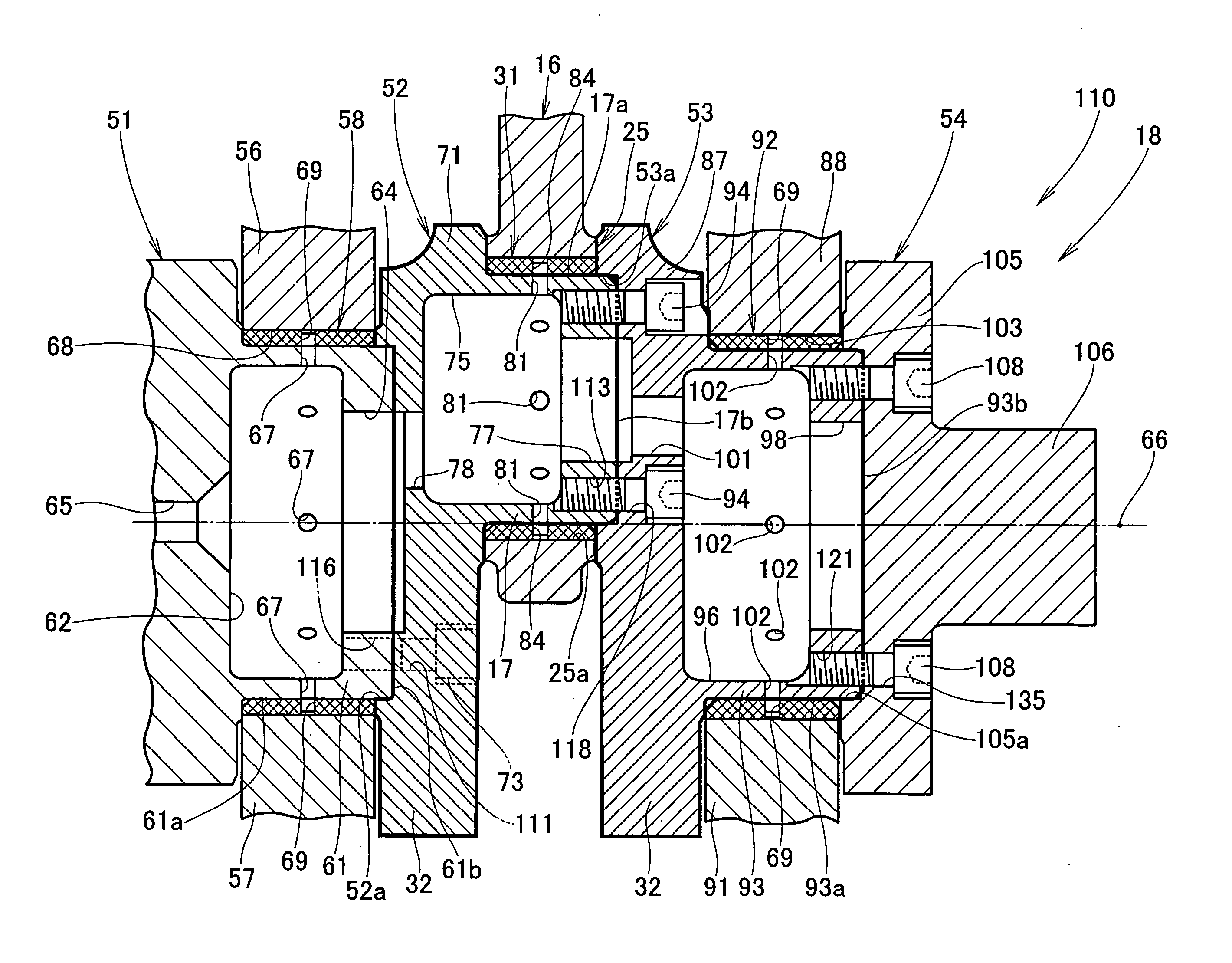
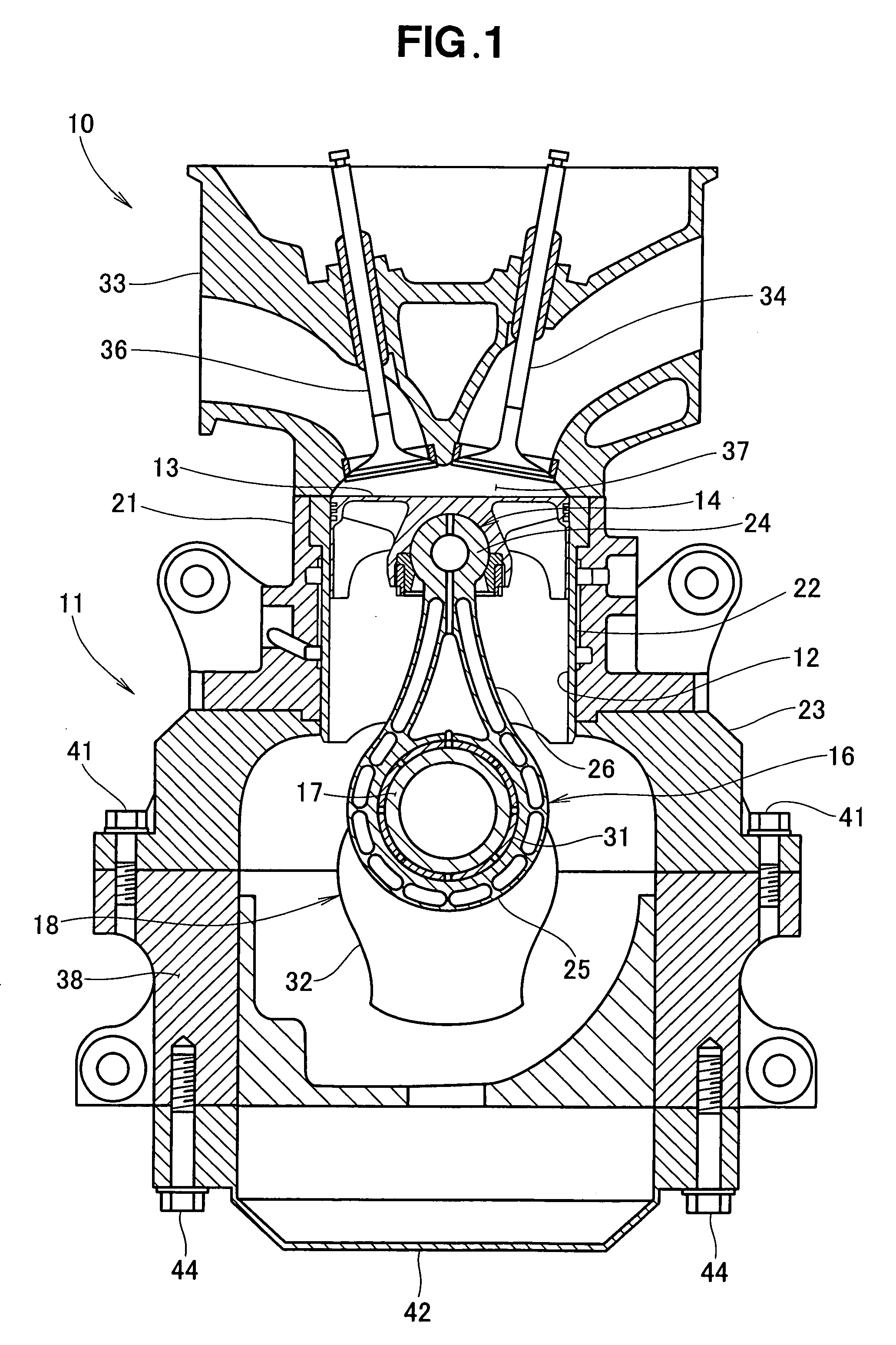
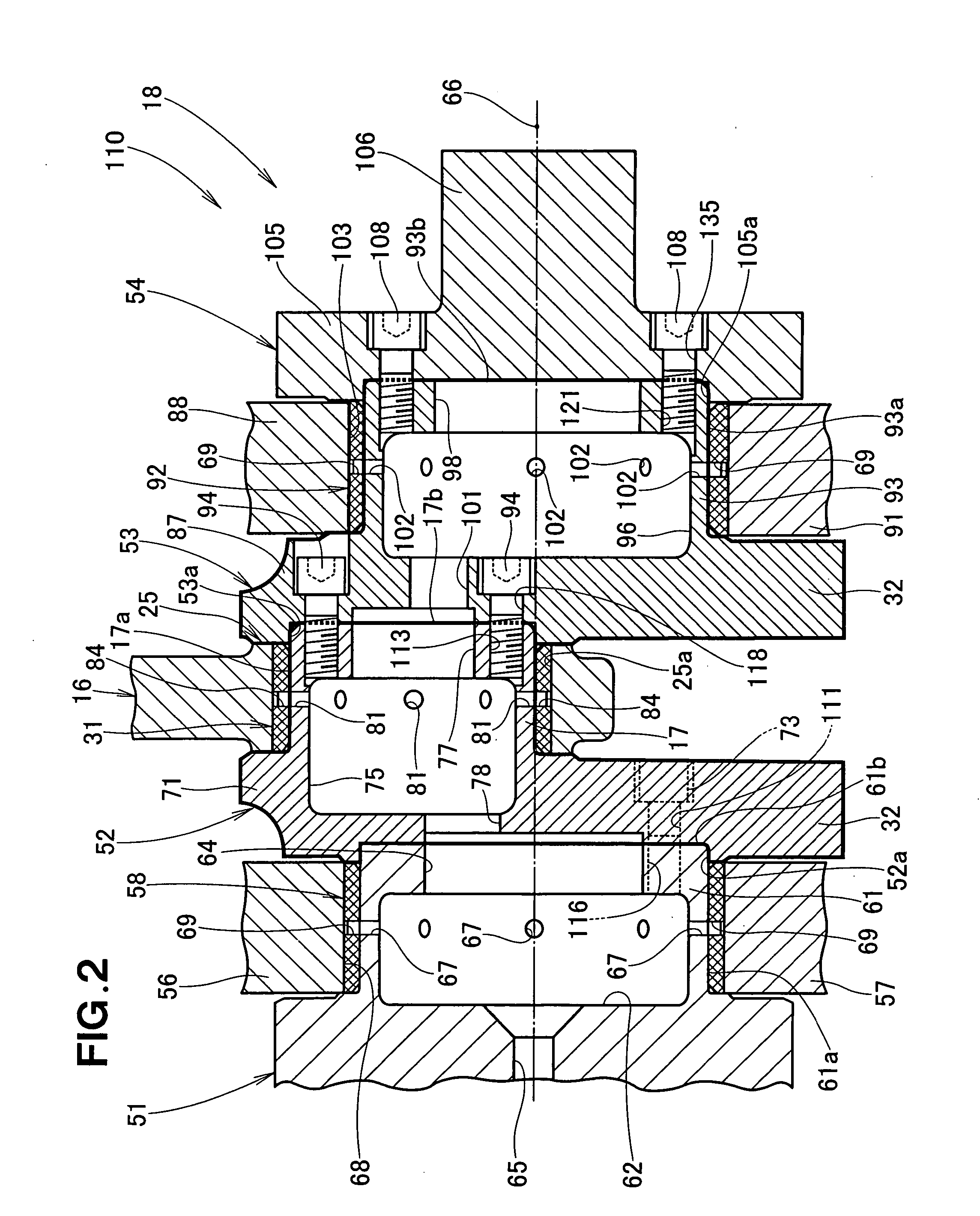
[0049]FIG. 1 is a sectional view of an internal combustion engine including an embodiment of a crankshaft assembly made using a crankshaft assembly making method of the present invention. The internal combustion engine 10 includes a cylinder block 11, a piston 13 reciprocatably inserted in a cylinder bore 12 formed in the cylinder block 11, a connecting rod 16 connected via a spherical joint 14 to the piston 13, and an assembled crankshaft 18 rotatably provided in a lower region of the cylinder block 11 and pivotably supporting the connecting rod 16 via a hollow crankpin 17.
[0050] The cylinder block 11 has an upper cylinder section 21, a cylindrical sleeve 22 fitted in the cylinder section 21 and having the cylinder bore 12 formed therein, and an upper crankcase member 23 fixed to the lower end of the cylinder section 21.
[0051] The connecting rod 16 is a one-piece member that has a small end 24 connected to the piston 13, a big end 25 connected to the crankpin 17 via a float beari...
PUM
 Abstract
Description
Claims
Application Information