Circuit for monitoring voltage of output terminal of hall sensor and circuit for supporting lens module actuating controller

Active Publication Date: 2021-06-10
SAMSUNG ELECTRO MECHANICS CO LTD
View PDF0 Cites 0 Cited by
  • Summary
  • Abstract
  • Description
  • Claims
  • Application Information

AI Technical Summary

Benefits of technology

[0007]An output voltage of a hall sensor may vary slightly, depending on a temperature of the hall sensor. As changes in an output voltage according to the temperature of the hall sensor are substantia

Problems solved by technology

As changes in an output voltage according to the temperature of the hall sensor are substantially independent of a position of the lens module, the

Method used


Image

  • Circuit for monitoring voltage of output terminal of hall sensor and circuit for supporting lens module actuating controller
  • Circuit for monitoring voltage of output terminal of hall sensor and circuit for supporting lens module actuating controller
  • Circuit for monitoring voltage of output terminal of hall sensor and circuit for supporting lens module actuating controller

Examples


Example

[0024]Throughout the drawings and the detailed description, the same reference numerals refer to the same elements. The drawings may not be to scale, and the relative size, proportions, and depiction of elements in the drawings may be exaggerated for clarity, illustration, and convenience.

DETAILED DESCRIPTION

[0025]The following detailed description is provided to assist the reader in gaining a comprehensive understanding of the methods, apparatuses, and / or systems described herein. However, various changes, modifications, and equivalents of the methods, apparatuses, and / or systems described herein will be apparent to one of ordinary skill in the art. The sequences of operations described herein are merely examples, and are not limited to those set forth herein, but may be changed as will be apparent to one of ordinary skill in the art, with the exception of operations necessarily occurring in a certain order. Also, descriptions of functions and constructions that would be well known...


PUM


Abstract

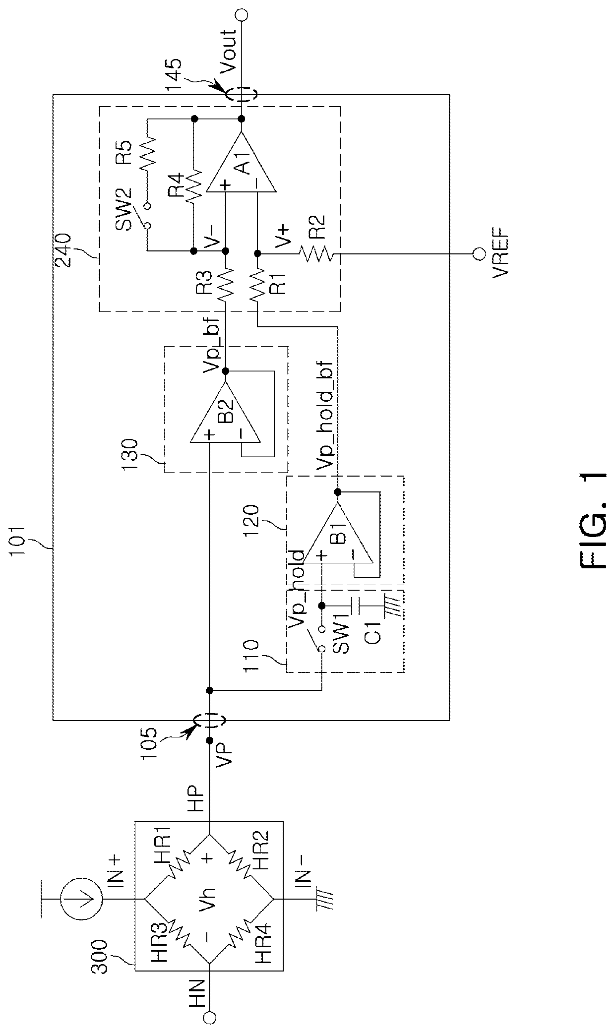
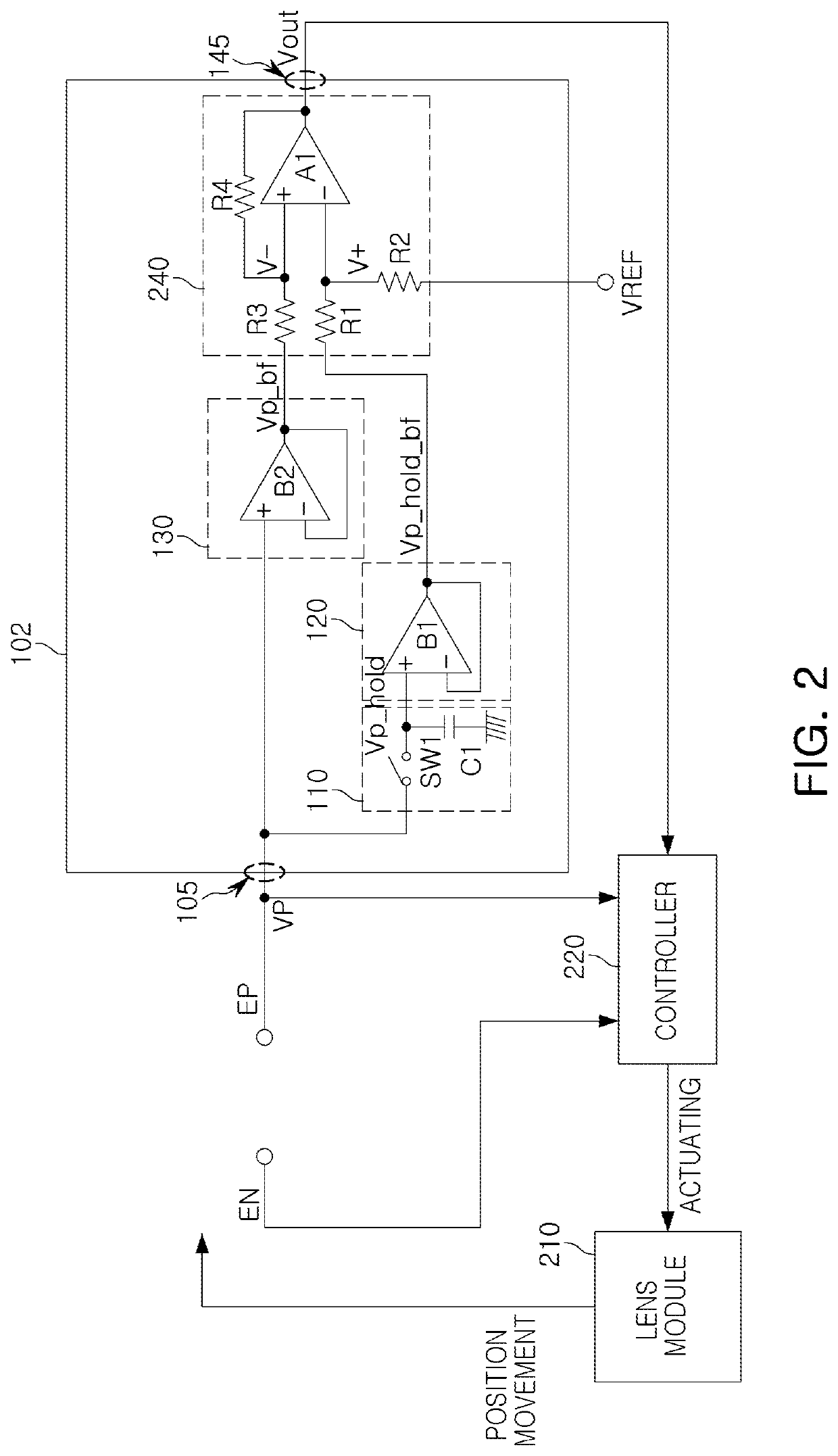
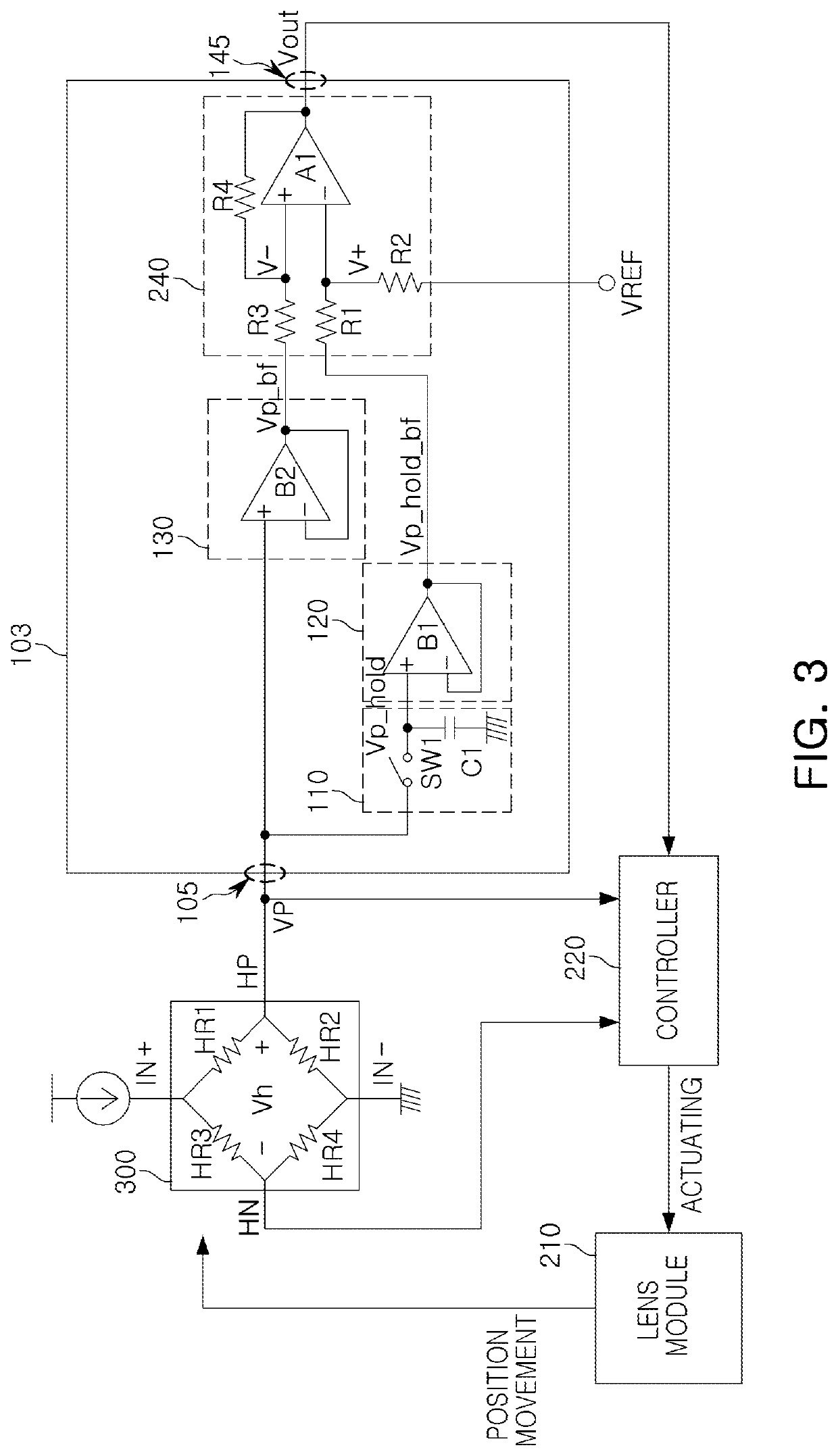
A circuit for monitoring an output voltage of a hall sensor includes an input port electrically connected to a first hall-sensor output terminal; an output port to output a monitoring voltage; a holder electrically connected to the input port to save the voltage of the input port; a first buffer including a first output terminal and first input terminal having an input impedance higher than an output impedance, having a voltage corresponding to a voltage of the first output terminal, and electrically connected to the holder; a second buffer including a second output terminal and second input terminal having an input impedance higher than an output impedance, having a voltage corresponding to a voltage of the second output terminal, and electrically connected to the input port; and an amplifier producing the monitoring voltage by amplifying a difference in voltages between the first output terminal and the second output terminal.

Description

CROSS-REFERENCE TO RELATED APPLICATION(S)[0001]This application claims the benefit under 35 USC § 119(a) of Korean Patent Application No. 10-2019-0161309 filed on Dec. 6, 2019 in the Korean Intellectual Property Office, the entire disclosure of which is incorporated herein by reference for all purposes.BACKGROUND1. Field[0002]The following description relates to a circuit for monitoring a voltage of an output terminal of a hall sensor and a circuit for supporting a lens module actuating controller.2. Description of Background[0003]In general, a technique for fixing a position relative to the outside of a lens module is widely used when the lens module moves according to a force received from the outside.[0004]For example, the camera module may include an optical image stabilizer device, which fixes a position of the lens module, even when the camera module is subjected to external force.[0005]A hall sensor may be used to measure position information of the lens module, and the hall ...

Claims


Application Information

Patent Timeline
IPC IPC(8): G01R33/00G01R15/20G01R33/07G02B7/02H04N5/225G01D5/14G01P1/00
CPCG01R33/0082G01R15/202G01R33/072G01P1/006H04N5/2257G01D5/142G02B7/02G02B7/028H04N23/54G01R33/0023G01R33/07G02B27/646G01R31/2829G01R19/0023G03B5/00H02P25/032G03B2205/0007H04N23/57
Inventor HEO, CHANG JAE
Owner SAMSUNG ELECTRO MECHANICS CO LTD
Why Eureka
Try Eureka