Rotor of permanent magnet rotating electric machine

a rotating electric machine and permanent magnet technology, applied in the direction of dynamo-electric machines, magnetic circuit rotating parts, magnetic circuit shape/form/construction, etc., can solve the problems of reduced inability to obtain satisfactory magnetic flux distribution, and reduced magnetic flux distribution. , to achieve the effect of improving the efficiency of rotating electric machine, increasing the fundamental wave effective value of induced electromotive force, and satisfying magnetic flux distribution

Inactive Publication Date: 2006-05-18
HITACHI LTD
View PDF16 Cites 33 Cited by
  • Summary
  • Abstract
  • Description
  • Claims
  • Application Information

AI Technical Summary

Benefits of technology

[0005] To achieve the above object, according to the present invention, in a rotor including permanent magnets and disposed inside a stator provided with a plurality of armature windings, one magnetic pole is constituted by each group of three or more of the magnets, and a total angle occupied by the group of magnets constituting one magnetic pole is in the range of 150 to 165 degrees in terms of an electrical angle. Such an arrangement is effective in not only realizing a satisfactory magnetic flux distribution such that magnetic fluxes are more efficiently concentrated toward the magnetic pole center, but also increasing the fundamental wave effective value of the induced electromotive force, whereby the efficiency of the rotating electric machine is improved. Further, since the magnets of each group are arranged in layout more concentrated toward the magnetic pole center position, the amount of magnets used is reduced and therefore a permanent magnet rotating electric machine can be provided at a lower cost.
[0006] Moreover, the magnet arranged on the magnetic pole end side is oriented to incline toward the magnetic pole center position. With this arrangement, since the distortion factor of the induced electromotive force waveform and the cogging torque are both reduced, a current value required for starting up rotation can be reduced and the rotation can be smoothly started up. Further, by setting an inclination angle of the magnet to be in the range of 2 to 6 degrees, the induced electromotive force can be effectively increased and therefore higher performance of the rotating electric machine can be realized.
[0007] Preferably, slots in which the magnets are disposed are shaped such that slits are formed between adjacent two of the magnets. With this arrangement, the leakage magnetic flux generated between adjacent two of the magnets is reduced and the utilization efficiency of the magnets can be increased. Further, by sealing a magnet fixing material in the slits, reliability of the rotor can also be increased. Additionally, by using a magnet in the form of a simple flat plate, the magnet cost can be cut.

Problems solved by technology

In the prior art described above, however, because the magnets are regularly arranged over the whole circumference of the rotor core such that they are inscribed in an outer circumferential circle of the rotor core, the magnetic flux distribution is dispersed to a large extent, and a satisfactory magnetic flux distribution cannot be obtained.
Also, the distortion factor of the induced electromotive force waveform is large and the fundamental wave effective value of the induced electromotive force is reduced, whereby the efficiency of a rotating electric machine is deteriorated.
It is hence difficult to start the operation in a smooth way.
In addition, because the permanent magnets are arranged over the whole circumference of the rotor, the number of magnets used is increased and the cost is pushed up.

Method used


Image

  • Rotor of permanent magnet rotating electric machine
  • Rotor of permanent magnet rotating electric machine
  • Rotor of permanent magnet rotating electric machine

Examples


Embodiment Construction

[0017] Embodiments of a rotating electric machine according to the present invention will be described below with reference to the drawings in connection with the case of the rotating electric machine having two poles.

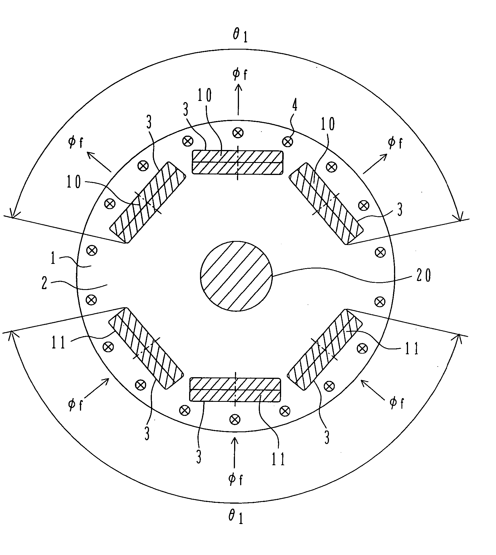
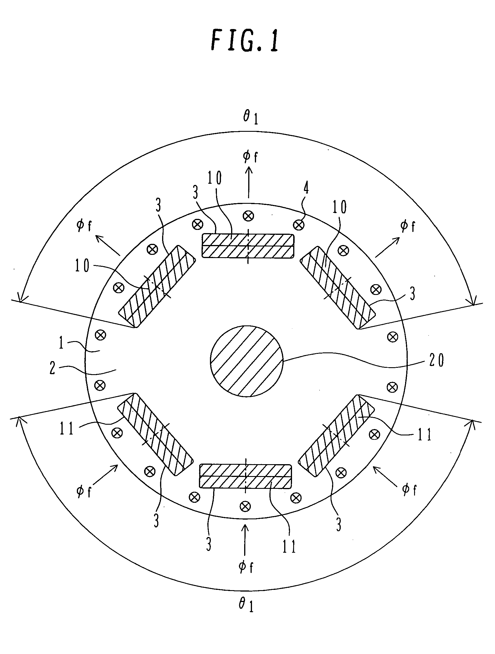
[0018]FIG. 1 shows the structure of a rotor of a permanent magnet rotating electric machine as one embodiment of the rotating electric machine according to the present invention. A rotor 1 comprises a rotor core 2, slots 3 in which magnets are disposed, N-pole permanent magnets 10, S-pole permanent magnets 11, a rotary shaft 20, and a plurality of damper windings 4 circumferentially disposed outside the magnets 10, 11. The rotor core 2 is a cylindrical laminated core formed by laminating a plurality of thin iron sheets one above another, which are each punched in a predetermined shape.

[0019] The N-pole permanent magnets 10 and the S-pole permanent magnets 11 are each a magnet generating magnetic flux Φf and are grouped in unit of three magnets per magnetic pole. Thos...


PUM


Abstract

In the prior art in which permanent magnets are regularly arranged over the whole circumference of a rotor core, a satisfactory magnetic flux distribution is hard to obtain, and the cogging torque and the distortion factor of the induced electromotive force waveform are large, whereby characteristics of a rotating electric machine are poor. Also, because the permanent magnets are arranged over the whole circumference, a large number of permanent magnets are required and cost reduction is difficult. A permanent magnet rotating electric-machine of the invention comprises a stator provided with a plurality of windings, and a rotor in which magnets are disposed in slots formed in a rotor core along an outer circumference thereof, the rotor core being fixed on a rotary shaft rotating inside the stator, and in which one magnetic pole is constituted by each group of three or more of the magnets. A total angle occupied by the group of magnets constituting one magnetic pole is in the range of 150 to 165 degrees in terms of an electrical angle.

Description

TECHNICAL FIELD [0001] The present invention relates to a rotor of a rotating electric machine employing permanent magnets, and more particularly to a magnet-embedded rotor in which magnets are embedded in a rotor core. BACKGROUND ART [0002] In the prior art disclosed in JP-A-2002-44887, a rotor is constructed by embedding Nd—Fe—B sintered magnets in a rotor core. The magnets are each in the form of a flat linear plate in a plan view and are arranged such that they are substantially inscribed in an outer circumference of the rotor so as to provide an almost polygonal shape. Further, the magnets are arranged over the whole circumferential of the rotor, and magnetic poles are each constituted by a plurality of magnets grouped in the same number. [0003] In the prior art described above, however, because the magnets are regularly arranged over the whole circumference of the rotor core such that they are inscribed in an outer circumferential circle of the rotor core, the magnetic flux di...

Claims


Application Information

Patent Timeline
Patent Type & Authority Applications(United States)
IPC IPC(8): H02K1/27H02K1/22H02K21/14
CPCH02K1/276
Inventor TANIGUCHI, TSUKASAMIKAMI, HIROYUKIKIKUCHI, SATOSHIJYORAKU, FUMIOHARADA, HIDEYUKI
Owner HITACHI LTD
Why Eureka
Try Eureka