Braking force retaining unit

a technology of retaining unit and braking force, which is applied in the direction of braking system, brake action initiation, vehicle components, etc., can solve the problem of time limitation

Active Publication Date: 2006-05-25
HONDA MOTOR CO LTD
View PDF8 Cites 35 Cited by
  • Summary
  • Abstract
  • Description
  • Claims
  • Application Information

AI Technical Summary

Benefits of technology

[0007] Then, a main problem that the invention is to solve is to provide a braking force retaining unit which can realize a smoother start of a vehicle while producing no such twist of the body and reducing the feeling of abruptness and physical disorder that are given to occupants of the vehicle.
[0014] According to the configuration described above, the retained brake hydraulic pressure is retained while the same hydraulic pressure is being gradually retained at the first reduction speed after the release of the depression of the brake pedal. Then, when the predetermined releasing condition is established, the retention of the brake hydraulic pressure is released by gradually reducing the retained brake hydraulic pressure at the second reduction speed. The second reduction speed used when implementing the release of the retention is faster than a speed at which the retained brake hydraulic pressure is reduced at the first reduction speed. Due to this, it becomes possible to release the braking force quickly while holding the smoothness. In addition, since when there are a plurality of brake pipe lines, there is provided no time difference in releasing timing between the respective brake pipe lines, the twist of the body is not generated at the time of releasing the braking force.
[0024] According to the first aspect of the invention, a smoother start of the vehicle can be enabled while producing no twist of the body when releasing the applied brakes and further reducing the feeling of physical disorder and abruptness.
[0026] In addition, according to the third aspect of the invention, the point in time when the release of brake hydraulic pressure is initiated is clarified, thereby making it possible to implement an appropriate release of brake hydraulic pressure.

Problems solved by technology

In addition, in the case of JP-A-2001-354126, in the event that a large time difference is set, since a behavior such as one in which a body of the vehicle is twisted in some way is generated in the crossed brake pipe lines, there is imposed a limitation on setting of time, and hence the compatibility of the reduction in a shock felt by the occupants when the applied brakes are released with the reduction in the behavior in which the body of the vehicle is twisted needs a certain compromise.

Method used


Image

  • Braking force retaining unit
  • Braking force retaining unit
  • Braking force retaining unit

Examples


Embodiment Construction

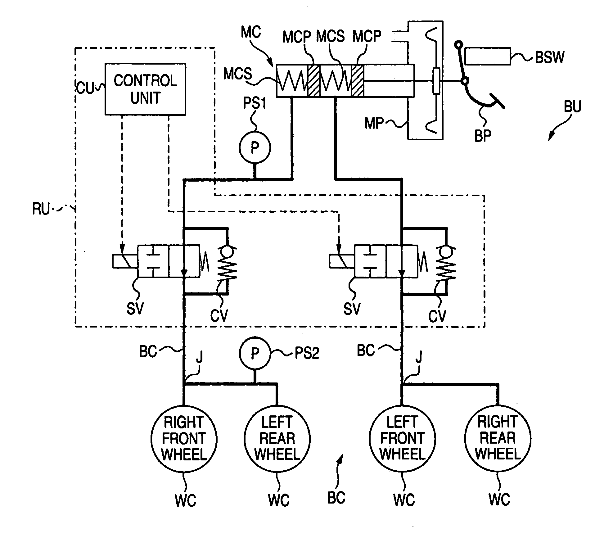
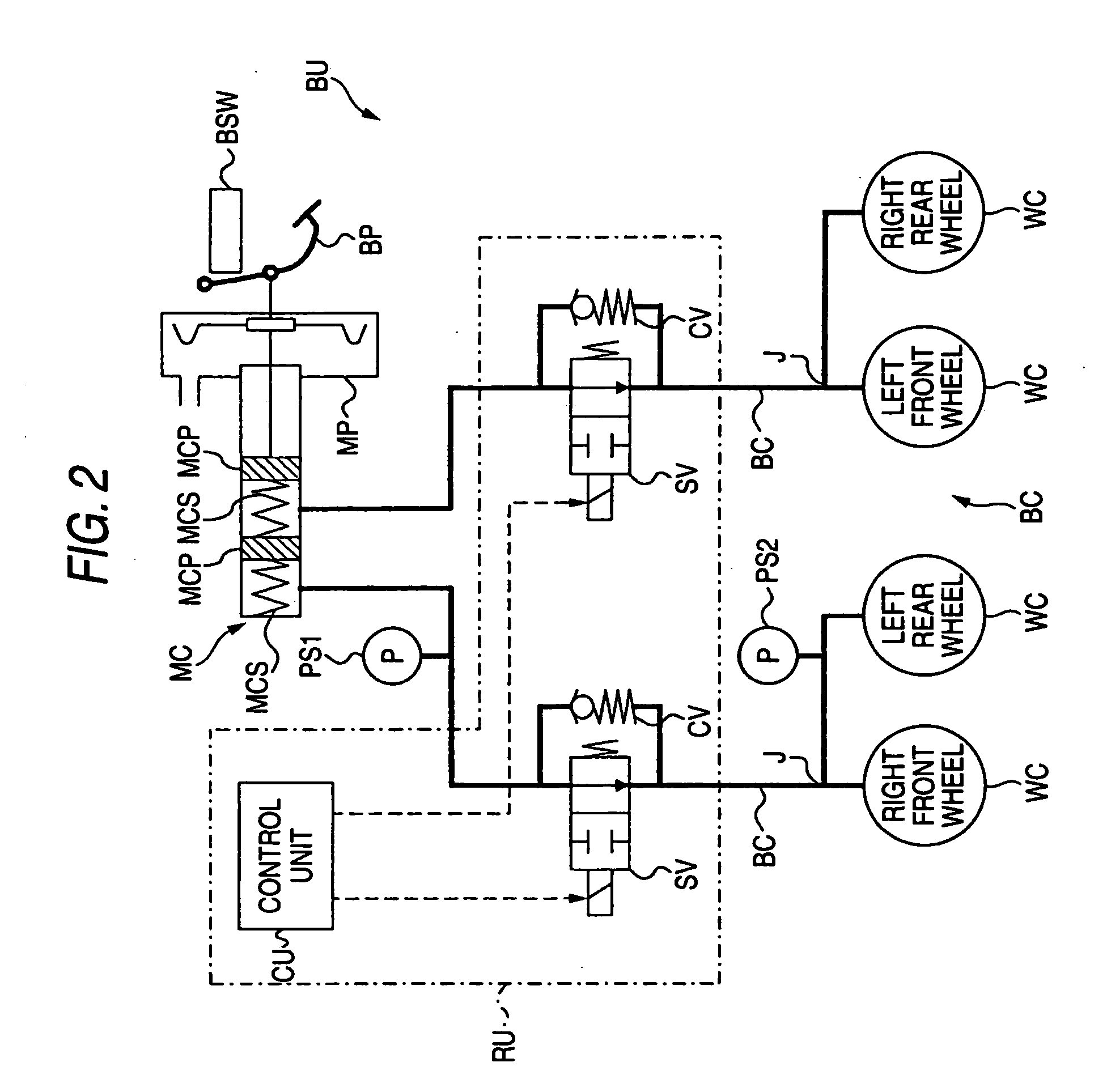
[0035] Hereinafter, a best mode (hereinafter, referred to as an embodiment) for carrying out a braking force retaining unit of the invention will be described in detail by reference to the drawings.

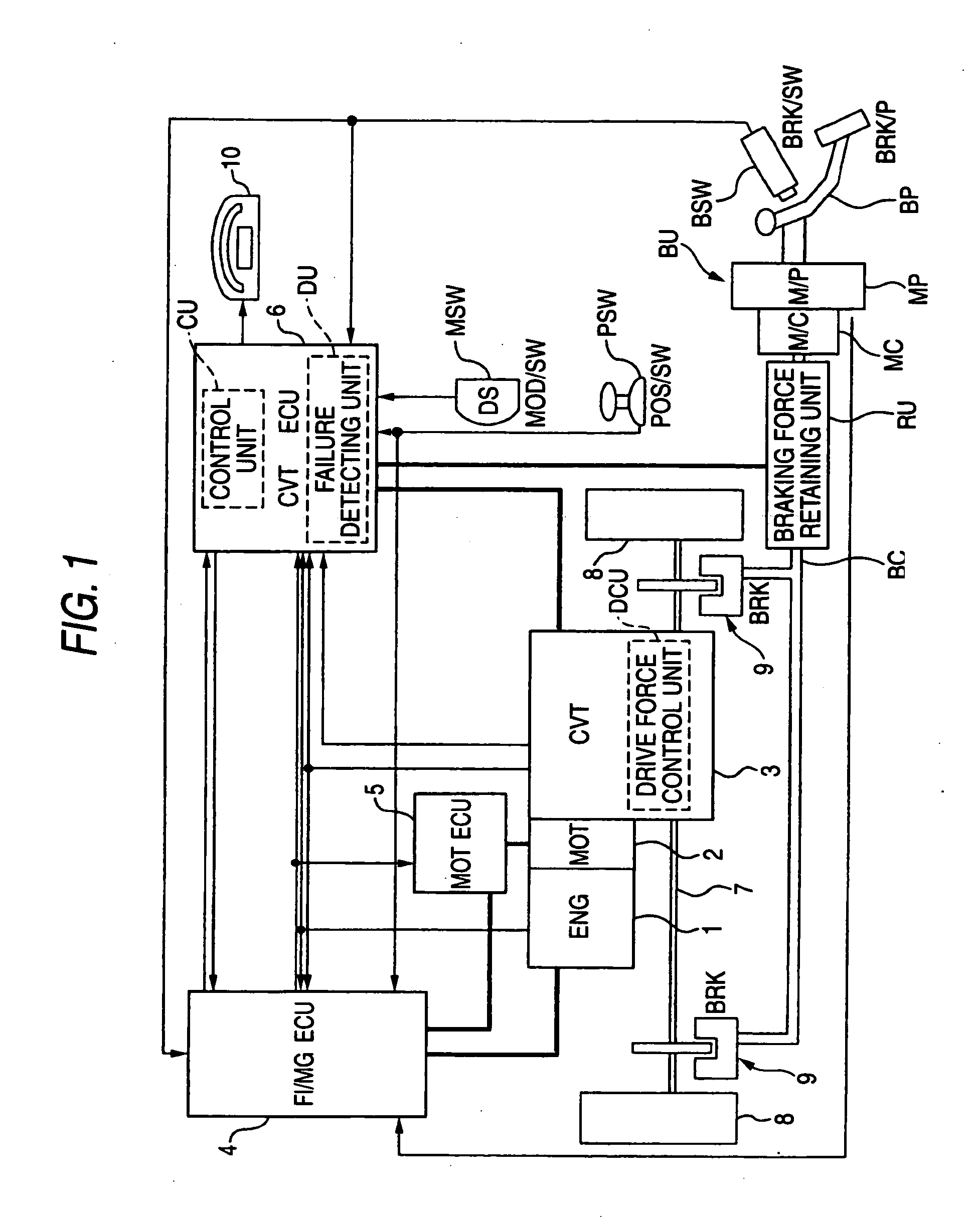
[0036] A braking force retaining unit of the invention is applied to a brake unit of a four-wheeled vehicle having a prime mover and continues to retain a brake hydraulic pressure at respective wheel cylinders until a predetermined releasing condition is established even after the depression of a brake pedal is released. A brake hydraulic circuit of the brake unit is divided into two systems or lines, and the braking force retaining unit is provided for each of the divided systems. Note that the vehicle has a drive force control unit which changes over a creeping drive force according to depressing conditions of the brake pedal between a large state and a small state when the prime mover is idling and the vehicle is moving at a predetermined vehicle speed or smaller. When used herein, cr...


PUM


Abstract

A braking force retaining unit has a cut-off valve and a control unit. The cut-off valve retains predetermined brake hydraulic pressure at the wheel cylinders until a predetermined releasing condition is established even after the depression of a brake pedal is released when a vehicle is stopped, whereas when the predetermined releasing condition is established, the brake hydraulic pressure so retained is released, when the depression of the brake pedal is released, the control unit controls the cut-off valve so as to retain the brake hydraulic pressure while reducing the retained brake hydraulic pressure at a first reduction speed. When the predetermined releasing condition is established, the control unit controls the cut-off valve so as to allow the brake hydraulic pressure retained at the wheel cylinders to be reduced at a second reduction speed which is faster than the first reduction speed.

Description

[0001] The present invention claims foreign priority to Japanese patent application no. P.2004-273152, filed on Sep. 21, 2004, the contents of which is incorporated herein by reference. BACKGROUND OF THE INVENTION [0002] 1. Field of the Invention [0003] The present invention relates to a braking force retaining unit which can retain a braking force even after the depression of a brake pedal has been released. [0004] 2. Description of the Background Art [0005] A braking force retaining unit is configured to include an electromagnetic or solenoid valve which operates electromagnetically at an intermediate position along the length of a brake hydraulic circuit so as to cut off the brake hydraulic circuit by supplying the solenoid valve with an electric current, whereby even after the driver releases the depressed brake pedal, brake hydraulic pressure (braking force) is retained at the wheel cylinders, so that the vehicle is, for example, prevented from moving backward from its own weig...

Claims


Application Information

Patent Timeline
Patent Type & Authority Applications(United States)
IPC IPC(8): B60T8/60
CPCB60T7/122B60T2201/06
Inventor OHSAKI, SEIJIISHIZUKA, HIROYASU
Owner HONDA MOTOR CO LTD
Why Eureka
Try Eureka